|
| |
TM 5-4210-233-14&P-1
5-66. APU GENERATOR-Continued
WARNING
Be careful when working on or with electrical equipment. Do not
be misled by the term "low voltage". Voltages as low as 50 volts
may cause death.
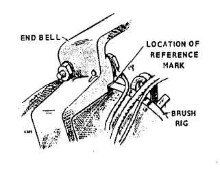
(18) With the end cover and band removed
to allow access to the rig, start the unit.
(19) Apply full rated load.
(20) Allow unit to reach full operating
temperature.
(21) Inspect brushes; they must be seated
across the brush face if we are to have
an accurate setting.
(22) Connect a voltmeter across the dc
terminals.
(23) Loosen the brush rig mounting screws
and rotate the rig to get the highest
voltage with full load.
(24)
Rotate the rig in one direction until the
voltmeter reading starts to decrease.
Mark this point.
(25) Repeat Step 20 in the other direction. Half the distance between the two marked points is the
neutral position.
(26) Shutdown unit.
f.
Adjustment.
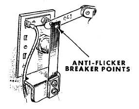
(1) The anti-flicker breaker points are located
on the left rear corner of the engine
crankcase. The camshaft opens these
points on every power stroke to add a
resistor in series with the generator field
windings (2). To adjust the points, crank
the engine until the points are at full
separation. Adjust the stationary contact
to .025 in. (.64 mm) gap. Retighten and
check the gap. When breaker plunger
guide and O-ring are removed, dip O-ring
in oil before reinstalling. Tighten guide to
25 to 28 ft Ibs (34 to 38 N·m).
(2) The adjustable flicker resistor is located
on the right side of the control box. If
flicker becomes excessive, adjust the
resistor by moving its slider. Adjust
resistor for minimum flicker with the
average load on the plant.
g.
Follow-on Maintenance.
(1)
Install APU (see para 4-207).
5-369
|