 |
|||
|
|
|||
|
|
|||
| ||||||||||
|
|
 TM 5-4210-233-14&P-1
5-78. APU INJECTION PUMP
This task covers:
a. Removal
c. Installation
b. Adjust
d. Follow-on Maintenance
TOOLS REQUIRED
EQUIPMENT CONDITION
Tool Kit, General Mechanics, Automotive
APU Removed (see para 4-207.)
(Appendix B, Section III, Item 1)
Gear Cover Removed (see 5-68.)
MATERIALS/PARTS REQUIRED
Lubricating Oil (Item 10, Appendix E)
Oil Ring Seal (Figure 21 1, Appendix E)
a. Removal.
(1)
Loosen screw and remove air housing panel.
(2)
Remove four capscrews, four flat washers,
plain housing panel, and nozzle housing panel.
(3)
Disconnect governor ball joint from injection
pump.
(4)
Tag and disconnect fuel hoses.
(5)
Tag and disconnect fuel line (1) from fuel
injection nozzle.
(6)
Cap all openings in pump, tines, and hoses.
(7)
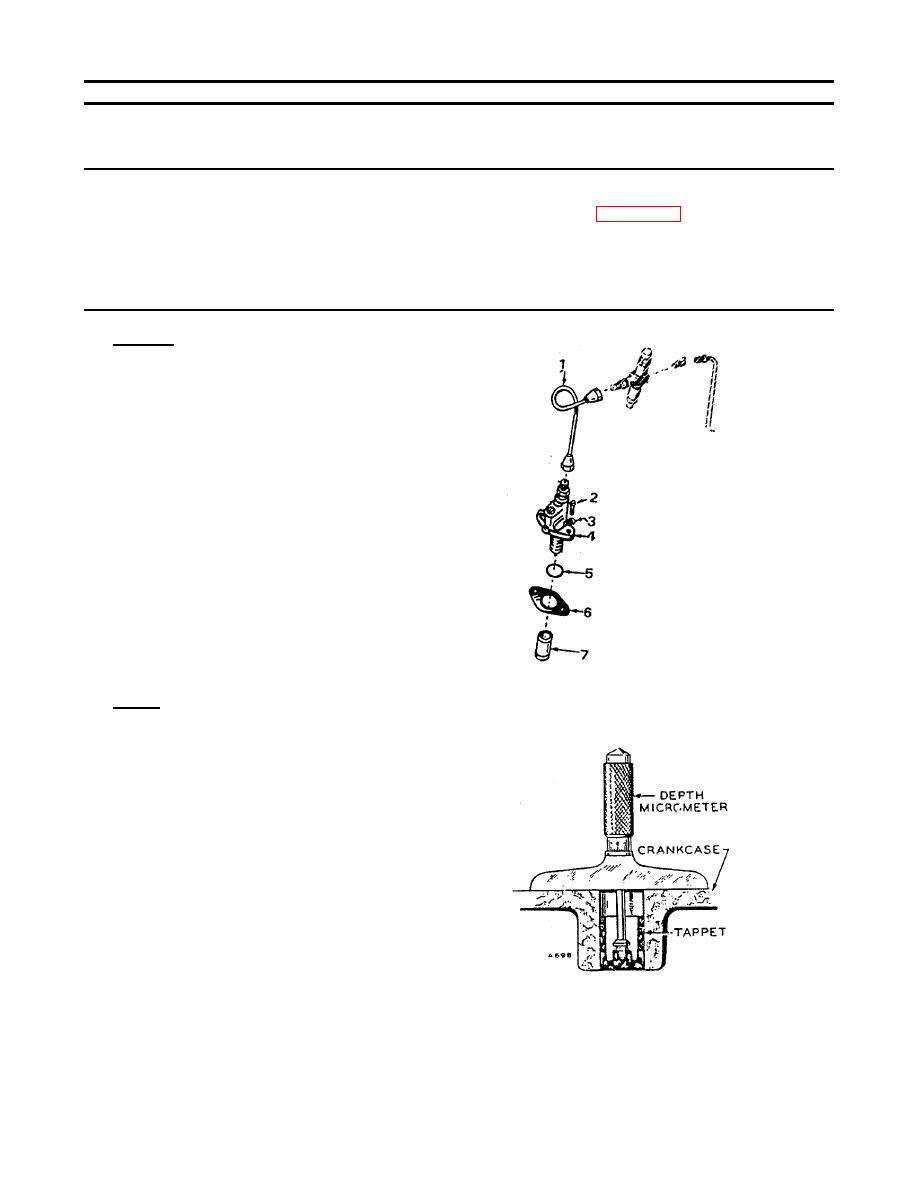
Remove two capscrews (2), two lockwashers
(3), injection pump (4), O-ring seal (5), shim(s)
(6), and valve tappet (7).
b. Adjust.
(1)
Install pump tappet (7) in recess in crankcase
and position flywheel on the port closing mark
(PC) of the compression stroke.
(2)
Using a depth micrometer, measure the
distance from the pump mounting pad on the
crankcase to the center of tappet.
(3)
Determine required number of shims by
subtracting 1.670 in. (42.42 mm) from
dimension obtained in step 2.
(4)
Select shims to achieve required thickness.
5-402
|
|
Privacy Statement - Press Release - Copyright Information. - Contact Us |
