|
| |
TRUCK SERVICE MANUAL
TM 5-4210-230-14&P-1
STEERING GEAR
back adjusting screw out one turn and measure
torque required to rotate worm shaft (17), thru 90
deg. each side of center of steering gear travel. This
torque must not exceed 1.7 Nm (15 in.lbs.). Tighten
adjusting screw and torque nut (38) to 95-109 N
m
(70-80 ft.lbs.), after tightening nut torque to rotate
worm shaft must rise .45-.79 Nm (4-7 in.lbs.) above
torque checked previously (Fig. 35).
30.
Apply a generous amount of clean wheel bearing
grease to bearing race inside side cover (58) to retain
bearing rolls; assemble forty-four bearing rolls.
Grease must retain rolls.
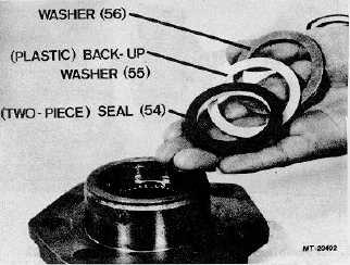
31.
Assemble washer (56), back-up washer (55), two-
piece seal (54) and retaining ring (53) into side cover
(58). Assemble two-piece seal (54) with "oil side"
towards retaining ring (Figs. 36 and 37).
Fig. 37
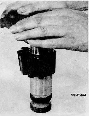
38.
Apply clean grease to short bearing area of sector
shaft (50) and insert into side cover (58); screw
adjusting screw (51) into side cover until it reaches
solid height. The side cover should rotate freely on
sector shaft with no appreciable axial movement
(Fig. 38).
Fig. 38
33.
Assemble nut (59) onto adjusting screw (51) a few
threads. (Final adjustment must be made later.)
34.
Assemble vent plug (60) in hole provided in side
cover (58), press vent plug in flush with side cover.
35.
Apply clean grease to side cover gasket (57) and
assemble onto side cover (58). Grease must hold
side cover gasket in place.
36.
Rotate worm shaft (17) to position rack piston (31) in
center of steering gear travel. Align center tooth on
sector shaft (50) with third notch from seal ring (29)
end on rack piston and assemble sector shaft with
side cover attached into housing (20); care must be
taken to not pinch side cover gasket and to be certain
that sector shaft goes thru housing bearing (21)
without knocking out bearing rolls (Figs. 39 and 40).
CTS-2717 Page 12
PRINTED IN UNITED STATES OF AMERICA
|