|
| |
TRUCK SERVICE MANUAL
TM 5-4210-230-14&P-1
INSTRUMENTS
FLEX-PRINTED CIRCUIT
One component of instrument cluster which is integral
with cluster body itself is the flexprinted circuit. This tough
flexible plastic film is cemented to cluster body to simplify
instrument wiring (25 electrical connections are replaced by
one). However, if the need should arise for electrical trouble
shooting, individual circuits on the printed circuit are easily
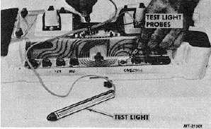
checked. This is accomplished with cluster removed (Fig. 12).
Fig. 12 Checking Printed Circuit Continuity
Testing
Obtain SE-2060-4 Test Light or equivalent tester and
position test probes on a selected circuit in a manner similar to
that shown in Fig. 12. If test light illuminates, circuit is
unbroken, or if test light fails to illuminate circuit is broken.
Check each circuit in turn and if a broken circuit is found,
instrument cluster body must be replaced.
Replacement
Since printed circuit is cemented to and integral with
instrument cluster body, the printed circuit and cluster body are
available for replacement as a complete assembly only. Where
replacement is required, obtain new instrument cluster body
assembly and transfer all gauges and light bulbs from old
cluster body to new. Individual parts of the instrument cluster,
available for service, are shown in Fig. 13.
SPEEDOMETER
The speedometer used on this vehicle indicates miles
and kilometers per hour. Distance traveled is recorded (in
miles*) on an odometer. Speedometer is driven by a semi-rigid
cable connected to a set of gears in vehicle transmission.
Specified gears match the particular truck model anti take into
consideration such other factors as
tire size and rear axle ratio, The semi-rigid cable which
connects transmission driven gear to the speedometer head
consists of an outer case and an inner core. Odometer records
up to 999,999 miles* and returns to zero. School bus models
record 99,999,9 miles.* (*Total metric speedometers record
kilometers.)
SPEEDOMETER ADAPTER
Should the need arise for changing a truck axle ratio or
tire size, a corresponding change must also be made to the
speedometer drive. This is accomplished by changing the
speedometer adapter and in some instances the driven gear in
the truck transmission. Information for finding the correct
adapter and driven gear can be found in the Speedometer
Section of the Parts Catalog.
TACHOMETER
An electrical or mechanical tachometer (not standard for
all vehicles) is also located in the instrument cluster to record
engine RPM (Revolutions Per Minute). This instrument enables
driver to keep engine speed within an efficient operating range.
The mechanical tachometer is driven by a flexible shaft
connected to an adapter or driving unit located on engine
(distributor shaft for gasoline engines or air compressor
injection pump, auxiliary shaft, etc. for diesel engines).
The electric tachometer reads the same as the
mechanical unit but receives electrical impulses by wire instead
of rotating cable. These impulses are received from a sender
unit mounted on the engine and using the mechanical
tachometer drive take off.
SPEEDOMETER AND TACHOMETER CABLES
A semi-rigid type cable is used for both speedometer and
tachometer on S-Series Trucks.
This cable consists of (1) an outer case or cable
assembly with nut and ferrule at lower end and a quick
disconnect ferrule at upper end, and 2) a wire wound flexible
inner cable or core assembly with squared drive at upper end
and floating tip (Fig. 14) at lower end. The floating tip which is
detachable from cable allows core to float and thereby minimize
thrust on speedometer or tachometer head. (Speedometer
cable assemblies are sometimes made in two sections for
assembly purposes.)
The cable outer case is formed from an inner nylon liner,
an intermediate ply of wire braid and an outer polypropylene or
polyethylene case (Fig. 15).
CTS-2735 Page 6
PRINTED IN UNITED STATES OF AMERICA
|

