|
| |
ENGINE DIVISION SERVICE MANUAL
TM 5-4210-230-14&P-1
will be necessary to increase or decrease belt tension
as required.
(5)
Before changing belt tension, repeat Step (3) several
times to become familiar with gauge operation.
Observe gauge reading each time operation is
repeated. Check tension of both belts when so
equipped.
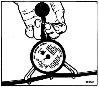
Fig. 64 Checking Belt Tension With SE-2312 Gauge
To establish tension of a loose belt apply SE-2312
gauge to belt and make the adjustment. Tighten belt until
proper area for belt is indicated at index mark on gauge. Lock
adjustment and recheck belt tension. Readjust as necessary.
When using SE-2312 belt tension gauge, remember to
set new belts (belt with less than two minutes running time) to
the NEW area on gauge face and used belts (more than two
minutes running time) to USED area on gauge.
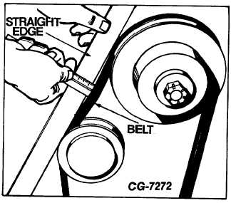
Belt tension may also be checked by using a straight
edge and scale as illustrated (Fig. 65).
Approximately 12.7 mm (½ inch) deflection should be
measured. The deflection measurement should be made
between pulleys at mid-point of longest belt span.
Fig. 65 Measuring Belt Tension
1. Straight Edge
2. Belt
INSPECT AIR PUMP AIR FILTER(S)
Inspect air pump centrifugal air filter; if clogged or
damaged, air pump centrifugal filter can be replaced as
follows:
(1)
Hold pump pulley from turning and remove pulley
mounting bolts.
(2)
Insert needle nose pliers and pull filter fan from hub
(Fig. 66). Care should be taken to prevent
fragments of the fan from entering the air intake hole.
(3)
Install new filter fan by drawing it on with the pulley
and pulley bolts (Fig. 67). Do not attempt to install
the filter by hammering or pressing it on.
(4)
Draw filter fan down evenly by alternately tightening
the pulley mounting bolts. Make certain that the
outer edge of the filter slips into the pump housing.
A slight amount of interference with housing bore is
normal.
(5)
Hold pulley from turning and torque pulley bolts to 34
N. m (25 ft. lbs.). The new filter may squeal up on
initial operation until its outside diameter sealing lip
has worn in.
CGES-215 Page 38
PRINTED IN UNITED STATES OF AMERICA
|