|
| |
ENGINE DIVISION SERVICE MANUAL
TM 5-4210-230-14&P-1
15C.
EGR Maintenance Indicating System (V-345 and
V-392 Engines Only)
This system is used to alert the vehicle operator, after
each 19200 Km (12,000 miles), that the EGR system must be
serviced to insure that it is operating properly.
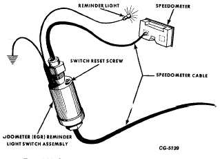
The system consists basically of a switch, or revolution
counting device, and an indicating light (Fig. 57).
Fig. 57 EGR Maintenance Indicating System
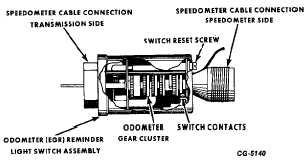
The switch is triggered by a counter mechanism,
similar to an odometer, which is connected in series with the
speedometer cable. After 19200 Km (12,000 miles), electrical
contacts inside the switch snap together and complete the
circuit to the indicator light (Fig. 58).
Fig. 58 Reminder Light Switch Assembly
The red indicator light, which has the words "Service
EGR" on the face, is mounted on the instrument panel. When
lighted, the letters are easily visible even in the daylight.
After the EGR system maintenance is performed, the
indicator light can be turned off and the switch reset by turning
the reset screw (Fig. 58) about 450 (¼ turn). This zeros the
switch's odometer gears and opens the electrical contacts.
The switch is then ready to count the next 19200 Km (12,000
mile) interval.
A circuit that tests the indicator light bulb during engine
starting is utilized, the same as the brake warning light.
16. Check Curb Idle Speed and Air; Fuel Mixture and
Adjust, as necessary.
Adjustment procedure with Exhaust Analyzer
Idle speed and fuel mixture adjustments must be made
with parking brake applied, air cleaner in place, transmission
in neutral and air conditioning "OFF".
When making idle adjustments on California engines,
disconnect vacuum hose from vapor storage canister and
plug end of hose. After idle adjustments have been made,
remove plug and reconnect hose to canister.
To compensate for fuel and temperature variations when
setting idle mixture, observe these precautions:
a.
Do not idle engine continuously for more than three
minutes at one time.
b.
After each three minutes of idling, increase engine
speed to 2000 rpm for one minute.
c.
Continue with idle adjustment procedure. Do not idle
engine for more than three minutes without repeating
Step b.
Winter grade gasolines, being more volatile than summer
grade, can yield vapors which result in excessively rich or
erratic
air/fuel
mixtures,
particularly
at
high
engine
temperatures. Because of this, care must be taken when
making carburetor idle mixture adjustments with the exhaust
analyzer. Attempts to adjust the idle mixture screw(s) leaner
to overcome a rich mixture caused by evaporation of winter
grade fuel at high engine temperatures can result in an
extremely lean mixture and associated starting and driveability
problems when vehicle is cold. Therefore, with winter grade
gasolines,
CGES-215 Page 32
PRINTED IN UNITED STATES OF AMERICA
|


