|
| |
ENGINE DIVISION SERVICE MANUAL
TM 5-4210-230-14&P-1
e.
Measure battery terminal D.C. voltage with engine at
idle speed and record.
f.
If coil positive terminal voltage is less than battery
terminal voltage by more than .5 volts, replace or
repair primary wiring, ignition switch or firewall
connector as required. Recheck coil output voltage.
If not satisfactory, proceed as follows:
g.
Measure ignition coil primary resistance. The
resistance from positive terminal to negative terminal
with ignition switch off should measure between 1.2
and 1.4 ohms. If resistance is outside these limits,
replace coil.
h.
Measure secondary resistance of ignition coil by
measuring between the positive terminal and the
secondary tower connector. The resistance should
measure between 9.4 and 11.1 thousand ohms. If
the resistance is outside these limits, replace coil.
i.
Off-Engine Coil Check: The ignition coil can be
removed from the engine and checked with SE2576 or
equivalent test equipment.
11. Check Initial Advance and Adjust if necessary.
a.
Connect timing light.
b.
Disconnect and plug vacuum advance hose.
c.
Start engine and operate until normal operating
temperatures are reached.
d.
Observe engine idle speed. Speed must be within
specifications (see Tune-Up Specifications); adjust
speed to specifications, if necessary.
e.
Observe initial advance with timing light.
f.
Loosen distributor clamp and adjust to specifications,
if necessary (see Emission Control System Tune-Up
Specifications). Tighten distributor clamp and
recheck initial advance.
Fig. 40 Typical Location of Timing Marks
g.
MV-446 engine, reconnect vacuum advance hose
and adjust speed to Tune-Up Specification, if
necessary.
Other
engines,
adjust
speed
to
specifications
with
vacuum
advance
hose
disconnected (Step b).
h.
Stop engine. Reconnect vacuum advance hose (if
necessary) and remove timing light.
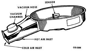
12. Check Operation of Inlet Air System Valve and
Service or Replace, if necessary.
Procedure for servicing the sensor controlled vacuum
chamber type air cleaner is as follows:
(Canada Scout Vehicles)
a.
Test should be conducted when ambient temperature
of the vehicle is less than 24 deg. C (75 deg. F) and
engine started cold. Air cleaner must have all hoses,
piping and cover in place. No leaks permitted.
Fig. 41 Sensor Controlled Vacuum Chamber Type Air
Cleaner
CGES-215 Page 24
PRINTED IN UNIT ED STATES OF AMERICA
|