|
| |
TRUCK SERVICE MANUAL
TM 5-4210-230-14&P-1
REASSEMBLY
15. Install the throttle operating shaft nut, tighten securely,
and bend tab on lock washer to retain nut.
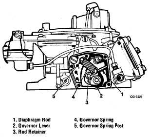
Governor Housing
1. Place the fast idle pin in position in the governor housing.
2. Insert the fast idle cam plunger spring in the plunger and
install the assembly in the governor housing.
3. Slide the fast idle cam assembly into position and install
the retainer.
4. Install the governor bypass jets and the governor line
fitting.
Figure 42 Interior View of Governor Housing
5. Install the governor spring pin in the same hole from which
it was removed if it were removed.
6. Position the governor diaphragm in the governor housing.
Position the diaphragm properly to avoid damage by the
screws. Install the cover with the screws and tighten securely.
Install new safety wire and a seal.
7. Place the governor lever in the housing and insert the
diaphragm rod on the stud. Install the rod retainer.
8. Housing is installed after the throttle body is assembled to
the main body.
Main Body
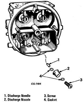
1. Drop the accelerating pump discharge needle into its well
(Fig. 43 governed carburetor).
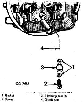
On nongoverned carburetors drop check ball into its well (Fig.
44 nongoverned carburetor).
2. Seat the needle with a brass drift and light hammer. Make
sure the needle is free.
Figure 43 Installing Pump Discharge Needle
3. Position the accelerating pump discharge nozzle gasket
and nozzle in the main body, then install the retaining screw
and gasket.
Figure 44 Installing Pump Discharge Check Ball
CGES-125-T Page 29
PRINTED IN UNITED STATES OF AMERICA
|