|
| |
TRUCK GROUP SERVICE MANUAL
TM 5-4210-230-14&P-1
GENERAL
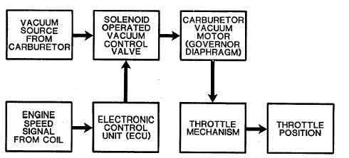
Electronic Vacuum Modulating Governor System (EVM)
The electronic vacuum modulating governor system
consists of a remote mounted electronic control unit (ECU), a
threeway solenoid vacuum valve and a vacuum diaphragm
attached to the carburetor throttle plates. The solenoid vacuum
valve and vacuum diaphragm are an integral part of the
carburetor. The ECU receives the engine speed signal from the
negative side of the ignition coil. This engine speed signal
switches the ECU (when governed engine speed is reached) to
allow current to flow through the solenoid vacuum valve. The
solenoid vacuum valve provides correct governor vacuum to the
vacuum diaphragm. The vacuum diaphragm acting against the
governor spring thereby controls the throttle position to regulate
engine speed (Fig. 25).
Internal clean air is supplied to both the solenoid side of
the solenoid valve and to the high pressure side of the governor
diaphragm. The cone-tipped side of the solenoid valve
connects the venturi and intake manifold vacuum to the low
pressure side of the governor diaphragm. In an underspeed or
current off condition, the solenoid return spring closes the
source vacuum port, thereby venting the low pressure side of
the governor diaphragm directly to the clean air source. In this
mode, the zero or near zero pressure differential across the
governor diaphragm prevents any governing action.
As the engine approaches governed speed, current is
applied to the solenoid which pulls the valve against the return
spring, closes the port to clean air and connects the governor
diaphragm to source vacuum. Modulation between the
extremes of solenoid valve full-off and full-on is accomplished
by varying the percentage on-time of the current to the solenoid.
This results in an average valve opening that is proportional to
percent on-time and provides the desired governing action. The
speed is factory preset within the electronic control unit.
Legend for Figure 25
1. Clean Air Port Open
2. Battery Supply
3. To Negative Side of Coil
4. Vacuum Port Closed
5. Low Pressure Side
6. Vacuum
7. Throttle Control Governor Diaphragm
8. High Pressure Side
9. Internal Clean Air
10. Clean Air Port Closed
11. Vacuum Port Open
Electronic Vacuum Modulating (EVM) Governor System Block Diagram
CGES-125-T Page 16
PRINTED IN UNITED STATES OF AMERICA
|