|
| |
TRUCK GROUP SERVICE MANUAL
TM 5-4210-230-14&P-1
GENERAL
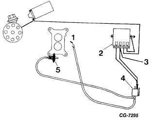
Figure 18 Deceleration Throttle Modulator System (Typical)
1. To Intake Manifold
2. Engine Speed Sensor Unit
3. From Ignition Switch
4. Solenoid Vacuum Valve
5. Throttle Modulator
Secondary Throttle Operation
The secondary throttle plates are operated by a spring-
loaded diaphragm which is controlled by vacuum from the right
primary venturi (Fig. 19 and 20). The secondary diaphragm
spring tends to hold the secondary throttle plates closed. When
engine air requirements approach the capacity of the two
primary venturis, increased vacuum from the right primary
venturi moves the secondary diaphragm, compressing the
diaphragm spring and opening the secondary throttle plates
(Fig. 20). As the secondary throttle plates open, the secondary
fuel system begins to discharge fuel and the engine is supplied
by all four carburetor venturis. When engine speed is reduced,
primary venturi vacuum acting upon the secondary diaphragm
is lessened, and the diaphragm spring starts closing the
secondary throttle plates. When the primary throttle plates are
fully closed, the secondary throttle plates are held closed
mechanically by design of the secondary connecting rod.
Governor (Distributor Spinner Controlled)
Internal Vacuum Type 4150G
A vacuum operated engine speed governor (Figures 21
and 22) is incorporated on the carburetor as a positive means
of controlling engine speed. The governor contains a throttle-
actuating mechanism attached to the primary throttle of the
carburetor through an overriding clutch. The throttle-actuating
mechanism consists
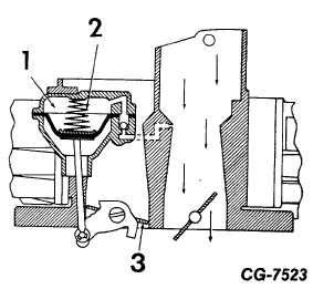
Figure 19 Secondary Throttle Operation (Low Speed or Light
Load)
1. Secondary Diaphragm
3. Secondary Throttle
Chamber
Plate
2. Diaphragm Spring Holds
Throttle Plate Closed
Figure 20 Secondary Throttle Operation (High Speed or Heavy
Load)
1. Increased Vacuum Moves Diaphragm Opening
Secondary Throttle Plates
2. Secondary Throttle Plate
of a diaphragm assembly, governor spring and governor lever
assembly. Below governing speeds the operator, through a
simple clutch arrangement on the throttle body of the
carburetor, controls the throttle body of the carburetor and
throttle plates in the usual manner. When governing speed is
reached, a combination of venturi and manifold vacuum acts on
the governor diaphragm to close the throttle plates.
CGES-125-T Page 12
PRINTED IN UNITED STATES OF AMERICA
|