|
| |
TRUCK GROUP SERVICE MANUAL
TM 5-4210-230-14&P-1
GENERAL
cavity vacuum when the throttle plates are opened to 50
degrees or greater. At this angle a hole in the throttle shaft and
the hole in the throttle body are aligned, permitting flow of clean
air from the air cleaner to the power valve cavity, thus reducing
cavity vacuum and insuring full fuel enrichment (Figures 12 and
13).
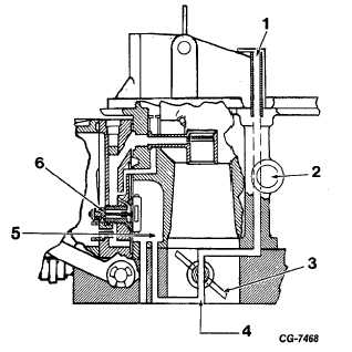
Figure 12 Modulator Valve in Open Position Power Valve Open
1. Clean Air Tube
4. Hole in Throttle Shaft
2. Air to Governor
Aligned with Hole in
3. Throttle Plate
Throttle Body
5. Vacuum Cavity
6. Two-Stage Power Valve
Acceleration Pump System
The accelerating pump is located in the bottom of the
fuel bowl. The function of the pump is to discharge fuel into the
carburetor upon acceleration demand in order to compensate
for the inertia of the fuel metering system with a temporary,
instantaneous enrichment of the air/fuel mixture. The pump
consists of a spring loaded diaphragm, a normally closed
needle check valve (discharge) and a normally open ball or
plastic check valve (inlet). The pump is actuated by a rotating
mechanical link mounted between the diaphragm and the
throttle lever assembly (Figures 14 and 15).
As the throttle is opened, a cam mounted to the throttle
lever rotates the pump lever, depressing the pump
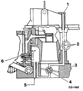
Figure 13 Modulator Valve in Closed Position Power Valve
Closed
1. Clean Air Tube
5. Vacuum to Power Valve
2. Air to Governor
Diaphragm
3. Throttle Plate
6. Vacuum Cavity
4. Hole in Throttle Shaft
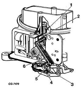
Figure 14 Acceleration Pump Fuel Flow (shown with inlet check
ball not used on early models).
1. Discharge Nozzle
4. Pump Inlet Check Ball
2. Pump Discharge Weight
5. Diaphragm
3. Diaphragm Return Spring 6. Discharge Passage
CGES-125-T Page 9
PRINTED IN UNITED STATES OF AMERICA
|