|
| |
ENGINE DIVISION SERVICE MANUAL
TM 5-4210-230-14&P-1
GENERAL
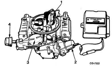
Figure 5 Model 4150EG Carburetor with Electronic Vacuum Modulating Type Governor
1. Choke Valve
3. Secondary Control Valve Assembly
2. Governor Solenoid Assembly
4. Control Valve Air Cleaner
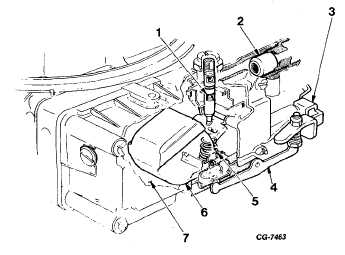
Figure 6 Typical Fuel Inlet System
1.
Needle and Seat
5.
Float Spring
Assembly
6.
Float and Lever
2. Filter Screen Assembly
3. Accelerating Pump
7.
Fuel Bowl
Operating Lever
4. Accelerating Pump
Cover Lever
Idle System
Primary Side. The 4150 series carburetors utilize two identical
idle systems, one for each primary bore. At idle, normal air
pressure in the primary float chamber causes
the fuel to flow through the idle system to the greatly reduced
pressure area below the throttle plate. Fuel flows from the float
chamber through the main jet into the small horizontal passage
that leads to a vertical passage.
Fuel flows up the idle well passage past the idle feed
restriction. The fuel then is mixed with incoming air from the
idle air bleed. This fuel and air mixture flows down a vertical
passage to the idle transfer passage and is discharged into the
throttle bore below the throttle plate. (Fig. 7)
Secondary Side. Because of driving habits, some drivers would
use the secondary side very little. If the secondary system
remains inoperative over long periods the system may become
blocked with gum and carbon formations. To prevent this
condition, an idle system is incorporated on the secondary side.
Fuel flows from the secondary fuel bowl through the
main jet, up the idle well and through the idle feed restriction.
Then it crosses a horizontal passage and blends with idle air
from the idle air bleed. This fuel-air mixture flows down a
vertical passage to the idle adjusting needle.
Part of this mixture flows into the idle discharge passage
and part into the idle transfer passage. The fuel-air is
CGES-125-T Page 6
PRINTED IN UNITED STATES OF AMERICA
|