|
| |
TRUCK SERVICE MANUAL
TM 5-4210-230-14&P-1
FRAMES
Riveting
Hot rivets are acceptable, as they can be more easily
driven with hand tools. Cold rivets should only be used where
tools of sufficient power to properly set the rivets are provided.
Rivets should be from 50% to 100% as heavy in diameter
as the total thickness of the plates to be riveted.
Welding
Electric arc-welding is recommended for all frame
welding. The reinforcements should be welded to the frame
after the reinforcements are riveted. All unused holes should
be filled with welding material. The welding rod should be
substantially the same material as that used in the frame.
Preparation Of Frame For Repair
Before welding the reinforcement to the cracked section
of the frame side rail, certain preparations are necessary to
insure strength and stableness of repair. To prevent further
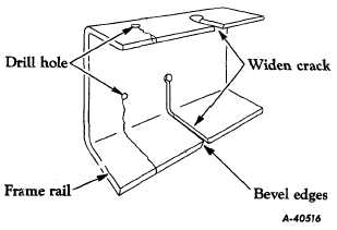
spreading of the crack, a hole should be drilled at the starting
point of the crack, Fig. 4. Widen the crack its full length,
using two hacksaw blades together. Groove or bevel both
sides of the crack to permit the weld to penetrate to the
surface
and
establish
a
solid
contact
between
the
reinforcement and the frame side rail. Grooving can be
accomplished by grinding or with a cape chisel.
Fig. 4-Showing Method of Drilling Frame Rail to Stop
Progress of Crack. Also shows Method of
Preparing Crack for Welding.
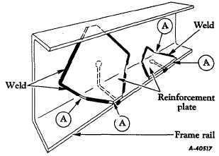
Fig. 5-Suggested Types of Reinforcing Plates and
Method of Attaching to Frame Rail.
IMPORTANT: Do not weld into the corners of the frame
or along the edges of the frame side rail flanges "A", Fig. 5.
Welding at these points tends to weaken the frame and
encourage development of new cracks.
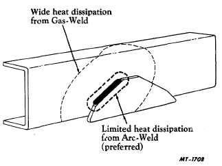
Use only the shielded-arc method for all frame welding.
Heat generated during welding is localized and burning of
material is minimized whenever this method is used. (Fig. 6)
Additional advantages are that the finished weld can be
ground, filed, and drilled as necessary.
With the reinforcement positioned in the frame side rail,
follow the welding patterns shown in Fig. 5 as closely as
possible.
Fig. 6-Weld Sample Showing Lower Heat Dissipation Possible
with Shielded Arc Welding.
CTS-2037-HA Page 4
PRINTED IN UNIT ED STATES OF AMERICA
|


