|
| |
TM 5-4210-230-14&P-1
VEHICLE MAINTENANCE
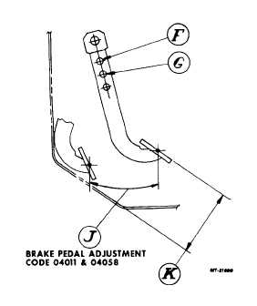
BRAKE PEDAL ADJUSTMENT Single
Hydraulic System (Codes 04011 & 04058)
Reference letters for brake pedal adjustment.
F.
Use this hole to attach clevis
to pedal on 4x2 & 4x4 vehicles.
G.
Use this hole to attach clevis
to pedal on 6x4 vehicles.
Brake pedal should have pedal
stroke "J" after pedal stop has
been adjusted to obtain pedal
height "K".
J.
226 mm (8.9")
4x2 & 4x4
vehicles
230 mm (9.1")
6x4 vehicles
K.
201.5 mm (7.9")
4x2 & 4x4
vehicles
206 mm (8.1")
6x4 vehicles
SPLIT HYDRAULIC SYSTEM
(Codes 04044, 04055 and 04059)
The brake pedal adjustment is at the booster control
valve (push rod) and clevis. Proper pedal height (travel) will
be obtained when the clevis is adjusted to 177.8 mm (7")
between booster mounting surface and clevis center opening.
MASTER CYLINDER (Brake)
Fluid level should be 6.4 to 12.7 mm (1/4 to 1/2") from
top of reservoir. Do not fill the master cylinder to the top of
reservoir.
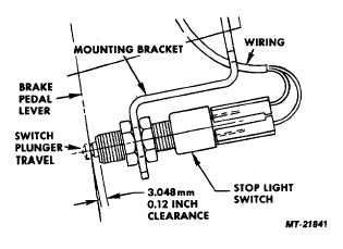
STOPLIGHT SWITCH ADJUSTMENT
The stoplight switch should be adjusted so that the
clearance between the switch body (not plunger) and pedal
lever is 3.048 mm (0.12"), when the brake pedal has been
properly adjusted
SPECIAL FLUID PRECAUTIONS
CAUTION
The
Hy-Power
and
Dual
Power
Brake
Systems consist of two completely separate
hydraulic systems operating with two different
and incompatible fluids; power steering fluid
and hydraulic brake fluid. Failure to observe
precautions preventing the contamination of
either system with fluid from the other will
result in the swelling and deterioration of
rubber
parts
leading
to
reduced
brake
performance and eventual failure.
To avoid fluid contamination, the following should be
observed:
1.
Use only fluids specified (or equivalent), and properly
identified.
2.
Add fluids only to the following locations:
a.
Power steering fluid to the power steering fluid pump
reservoir.
b.
Brake fluid to the brake master cylinder.
4
|