|
| |
ENGINE DIVISION SERVICE MANUAL
TM 5-4210-230-14&P-1
ENGINE
50. Install fuel line with filter between the fuel pump and
carburetor. Secure fuel line bracket to right cylinder head
cover with screws and washer.
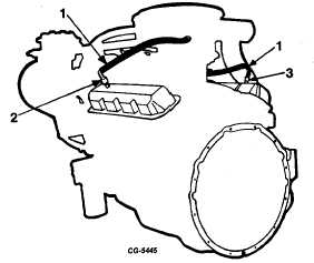
51. Install flame arrestor and hose to left cylinder head cover,
Figure 153. Install opposite end of hose to air cleaner after its
installation.
Fig. 153 Flame Arrestor and Crankcase Ventilator Valve
Installation
1. Hose
2. Flamearrestor
3. Crankcase ventilator valve
52. Install crankcase ventilator valve in right cylinder head
cover and connect hose to valve and tube fitting in
carburetor, Figure 153.
53. Install engine water inlet and gasket with two bolts and
lockwashers.
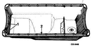
54. Install oil pan on crankcase using the liquid gasket
material, Figure 154.
NOTE: Caution should be taken not to apply
excessive amounts which could contaminate the
engine oil.
55. Install oil filter and cooler with gasket, if so equipped, to
the crankcase. Also install air compressor oil feed line to
crankcase. Refer to Figure 27 for location.
NOTE: If the vehicle is not equipped with an oil cooler,
install filter base and filter with gasket.
56. Place the starting motor into the flywheel housing and
secure with two bolts and lockwashers.
Fig. 154 Application of Liquid Gasket Material on Oil Pan
1. 1/8" bead at corners and both ends
2. 1/16" bead on both sides
57. Install power steering pump bracket and adjusting
bracket. Refer to Figure 25.
58. Loosely install power steering pump with side bracket to
pump mounting bracket.
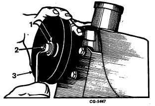
59. Place power steering pump pulley on shaft aligning the
pulley with the keyway and tap gently with a soft hammer.
Use a 5/16" x 18" x 1-1/4" long bolt and washers to pull
the pulley against the shoulder of the pump, Figure 155.
Then replace the long bolt with the shorter bolt and
tighten to specified torque.
Fig. 155 Pulling Power Steering Pulley Against Shoulder of
Pump
1. Washers
3. Pulley
2. Bolt
CGES-210 Page 63
PRINTED IN UNITED STATES OF AMERICA
|