|
| |
ENGINE DIVISION SERVICE MANUAL
TM 5-4210-230-14&P-1
ENGINE
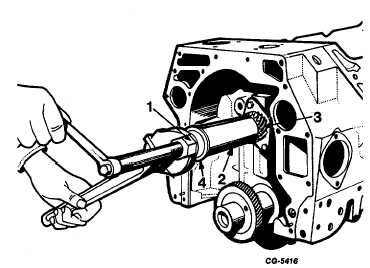
Fig. 123 Installing Distributor Drive Gear Using SE-1900 Tool
Set with Thrust Bearing
1.
Nut
3.
Distributor drive gear
2.
Sleeve
4.
Thrust bearing
2.
Install fuel pump cam against distributor drive gear
on camshaft using SE-1900-14 sleeve with SE1900-
16 adapter and thrust bearing in a manner similar to
Step 1.
3.
Install camshaft gear against fuel cam on camshaft
using SE-1900-14 sleeve with SE-1900-16 adapter
and thrust bearing in a manner similar to step 1.
4.
Install camshaft gear alien screw and torque to
specified torque. See "Torque Chart."
Crankshaft Bearings
The bearing inserts used in this engine are selective
fit and require no line reaming upon installation. The bearings
are available for service in standard and undersizes for use on
journals that have been reground.
If inspection revals badly worn or scored bearings,
replace the bearings. The installation of new bearings must be
closely checked to maintain the proper clearance between the
journal and the bearing surface. A convenient and accurate
method for checking the clearance is with the use of
Plastigage.
A. General Fitting Procedures
When wear reduces the bearing-tocrankshaft running
clearance, undersize precision-type bearing shells should be
installed. Premature bearing failure will result from attempts
to reduce journal-to-bearing running clearances by reworking
bearing caps, bearings or both. Such reworking will alter the
engineered fit of the bearing shells in their bores and destroy
the specifically desired "crush."
When installing precision-type connecting rod or
main bearings, it is important the bearing shells fit tightly in
the bore. The bearing manufacturer makes the diameter at
right angles to the parting line slightly larger than the actual
diameter of the bore into which they are assembled to
accomplish this. When the assembly is drawn up tight, the
bearing is compressed assuring a positive contact between
the bearing back and the bore. This increased diameter is
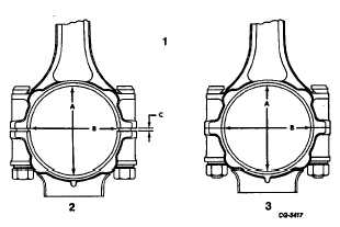
referred to as bearing "crush," Figure 124.
Fig. 124 Illustrating Bearing Crush
1.
Difference between
2.
Diameter (A) at
diameters (A) and
right angles to
(B) is bearing
parting lines
crush (C)
greater than dia-
meter (B).
3.
With bearing cap
drawn up tight
diameters (A) and
(B) equal.
CGES-210 Page 49
PRINTED IN UNITED STATES OF AMERICA
|