|
| |
ENGINE DIVISION SERVICE MANUAL
TM 5-4210-230-14&P-1
ENGINE
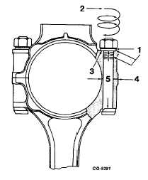
to a specified torque is to obtain tension in the bolt, Figure 98,
which in turn developes a clamping load or preload that
exceeds any possible loading imposed on parts due to engine
RPM. In other words, the connecting rods must "hang on" to
the crankshaft and suffer all the strains of intertia and cylinder
combustion impulse without permitting the least movement or
flexing of the rod cap, bolts or nuts. At the same time, torque
applied must be within the capacity of the parts (bolt, nut,
caps and connecting rods) to withstand these loads.
Fig. 98 Connecting Rod Cap and Bolt Details
1.
Friction
4.
Clamped
2.
Torque
5.
Tension
3.
Washer
In tightening connecting rod bolts and nuts to their
specified torque figure, a definite loading is obtained between
the connecting rod and cap. Specially designed bolts, nuts
and washers manufactured from selected materials permit the
application of this loading without undue stretching of bolts.
There is a relationship between the torque specifications and
clamping effect or load to be applied providing certain
conditions exist.
These conditions center largely around the belt itself
and its care, pointed out as follows:
1.
Bolt and Nut Thread Condition:
Threads that are dry, excessively rough, battered or
that are filled with dirt require considerable effort just to rotate
the nut. Then when the clamping load is developed or the bolt
tension is applied, the torque reading mounts rap o-idly
(due to thread friction) to the specified figure without
approaching the desired bolt tension and maximum clamping
effect. Under these conditions the desired torque reading is
obtained, but the clamping effect might be far below
requirements, leading to bearing failure or to connecting rod
bolt breakage. The proper bolt tension and clamping effect
can never be attained if the nut is dry. The nut and bolt must
have a film of lubricant in the thread section to be considered
lubricated. It is recommended that new connecting rod bolts,
nuts and washers be used during reassembly. Due to the
close fit of the connecting rod nuts on the bolts, the slightest
thread imperfection increases the friction to the extent that
incorrect bolt tension is likely.
Connecting rod bolts and nuts must be cleaned of all
foreign matter including the anti-rust materials that may be in
the threads. Apply light engine oil to the threads to lubricate
before installation.
2.
Tightening of Connecting Rod Bolts, Nuts and
Washers
Tighten the connecting rod bolts, nuts and washers
alternately with the torque wrench to the specified torque.
Then release the torque load to zero and retorque to specified
torque. See "Torque Chart." If nut is overtightened enough to
stretch the bolt, the nut and bolt both must be replaced. Use
new rod bolts, nuts and flat washers in major engine overhaul.
The application of specified torque to any particular
bolt or nut which serves to hold or clamp two parts together
should be accomplished with a torque wrench known to be
accurate.
Piston Rings
The pistons used in the V-type engines have three
piston rings located above the piston pin. The compression
rings are located in the top grooves while the lower groove
accommodates the oil control ring. Select the proper rings for
the size of pistons to be used.
Prior to installing the rings on the pistons, each ring
must be checked for proper ring gap. Push the ring down into
the cylinder bore making sure the ring
CGES-210 Page 36
PRINTED IN UNITED STATES OF AMERICA
|