|
| |
ENGINE DIVISION SERVICE MANUAL
TM 5-4210-230-14&P-1
ENGINE
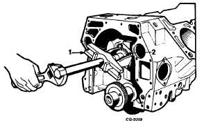
Fig. 66
1. Puller
2. Distributor Gear
69.
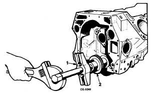
Use SE-1368 Puller to remove the crankshaft gear,
Figure 67. If necessary, use an adapter or heavy flat
washer between the crankshaft and puller screw to
prevent damage to the internal threads.
Fig. 67 Using SE-1368 Puller to Remove Crankshaft Gear
1. Puller
2. Crankshaft gear
70.
The crankshaft bearing caps are numbered and
arrowed to the front to identify their respective positions
for reinstallation. The number three bearing cap
accommodates a thrust flange to limit crankshaft end
play, Figure 68. Remove bolts from bearing caps and
remove all main bearing caps.
71.
Lift the crankshaft straight up and out of the cylinder
block. Remove upper bearing inserts.
Fig. 68 Main Bearing Cap Removal
1. Number
3 main bearing cap
2. Thrust flange
ENGINE OVERHAUL
Cylinder Block
One of the most important phases of engine
reconditioning is the thorough cleaning and inspection of the
cylinder block.
Each machined surface of the cylinder block should be
cleaned of all old gasket material. The pipe plugs which seal
the oil passages should be removed and all passages
thoroughly cleaned.
Remove the main oil gallery plug and use SE-2334-2
Brush (3/8" diameter) to clean the main oil gallery, Figure 69.
Replace oil plug after coating with a suitable nonhardening
sealing compound.
Fig. 69 Cleaning Main Oil Gallery with SE-2334-2 Brush
1. Tappet oil galleries
3. Brush
2. Main oil gallery
CGES-210 Page 25
PRINTED IN UNITED STATES OF AMERICA
|