|
| |
ENGINE DIVISION SERVICE MANUAL
TM 5-4210-230-14&P-1
ENGINE
23.
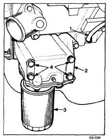
Remove bolts and flat washers securing oil filter and
cooler (if so equipped) to the crankcase, Figure 27.
Remove oil filter, cooler and gasket.
NOTE: If the vehicle is not equipped with an oil
cooler, the filter and filter base may be removed
by removing three bolts and flat washers.
Fig. 27 Oil Cooler and Filter Removal
1. Oil feed to air compressor
2. Oil cooler
3. Oil filter
4. Mounting bolts
24.
Remove oil feed line to air compressor, Figure 27.
25.
Remove low temperature vacuum control valve,
exhaust gas recirculating valve, gasket and hoses, if so
equipped. Cap or plug all openings.
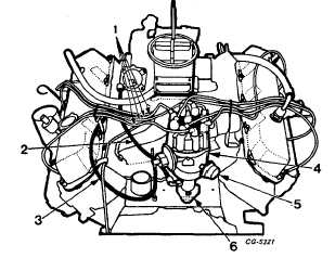
26.
Disconnect the distributor high tension wires at the coil
and spark plugs. Always grasp spark plug boat and
use a twisting motion when removing spark plug cables
so as not to destroy resistance wire termination.
Remove the wires with the slideout brackets on both
cylinder head covers and remove the distributor cap
and wires as an assembly, Figure 28.
Fig. 28 Distributor and Wiring Removal
1. High tension wires
2. Governor line
3. Vacuum line
4. Distributor
5. Filter
6. Hold down bracket
27.
Loosen the distributor hold-down bolt at the crankcase,
Figure 28. Disconnect the vacuum line and governor
line at the carburetor. Remove the distributor, governor
line, vacuum line and "O" - ring.
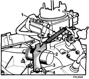
28.
Remove carburetor return spring and bracket from
intake manifold, Figure 29.
Fig. 29 Removing Return Spring and Bracket
1. Return spring
2. Bracket
3. Bolt
4. Lockwasher
CGES-210 Page 15
PRINTED IN UNIT ED STATES OF AMERICA
|