|
| |
ENGINE DIVISION SERVICE MANUAL
TM 5-4210-230-14&P-1
ENGINE
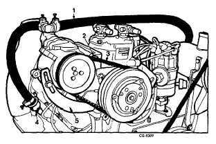
Fig. 16 Air Pump Removal
1. Hose to left head check valve
2. Mounting bolt
3. V-belt
4. Right head check valve
5. Adjusting strap
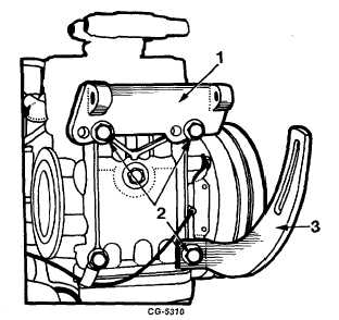
Fig. 17 Removing Air Pump Brackets
1. Bracket
2. Bolts
3. Adjusting Strap
12.
Remove air pump mounting brackets by removing bolts
and flat washers. Remove adjusting strap and spacer
by removing bolt and flat washer, Figure 17.
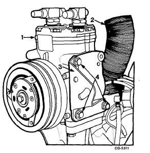
13.
Remove idler pulley bracket from freon compressor by
removing bolts and flat washers, Figure 18.
NOTE: Bottom bolts have two hardened flat
washers each.
14.
Remove shroud hose from exhaust manifold, Figure
18.
15.
Remove freon compressor from bracket by removing
four bolts and lockwashers, Figure 19.
Fig. 18 Removing Freon Compressor Idler Pulley Bracket
1. Freon compressor
2. Shroud hose
3. Bracket
4. Bolts
CGES-210 Page 12
PRINTED IN UNITED STATES OF AMERICA
|