|
| |
ENGINE DIVISION SERVICE MANUAL
TM 5-4210-230-14&P-1
2.
Test for Spark at plug.
Disconnect high tension cable from one spark plug.
(always grasp spark plug boot and use a twisting
motion when removing plug cables so as not to
destroy resistance wire termination.) Insert extension
adaptor into boot and engage in cable terminal.
Using insulated pliers, hold plug cable to create
about 13 mm (1/2") gap between extension adapter
and engine (Figure 47). Have an assistant crank
engine. Observe for spark across gap.
Test at least two cables.
If spark occurs, ignition system is functioning. Check
spark plugs and ignition timing. Then look elsewhere
(engine condition, fuel system, etc.) for problem.
If no spark occurs, proceed to step 3.
Fig. 47 Checking for Spark at Plug
1. Battery
3. Ignition Coil
2. Ignition Switch
4. 13mm (1/2 in)Gap
3.
Test for spark at distributor cap. Disconnect high
tension
cable
from
center
tower
terminal
of
distributor cap. Insert extension adapter into boot
and engage in cable terminal. (Figure 44). Using
insulated pliers, hold cable to create about 13mm
(1/2") gap between cable terminal and engine (Figure
47). Have an assistant crank engine. Observe for
spark across gap.
If spark occurs, problem lies in distributor cap, rotor
or spark plug cables. (See Secondary Circuit
Inspection).
If no spark occurs, proceed to step 4.
Fig. 48 Checking for Spark at Distributor Cap
1. Battery
3. Ignition Coil
2. Ignition Switch
4. 13mm (1/2 in.) Gap
4.
Check trigger wheel-to-sensor air gap
Remove distributor cap rotor and shield. "Bump"
starter to align one of the trigger wheel teeth with the
sensor coil (trigger wheel tooth perpendicular to flat
surface of sensor) as shown in Fig. 49. Check air
gap between trigger wheel tooth and sensor (see
SPECIFICATIONS). If air gap is to specifications,
proceed to step 5.
If air gap is out of specification, adjust air gap and
repeat step 3. If there is still no spark, proceed to
step 5.
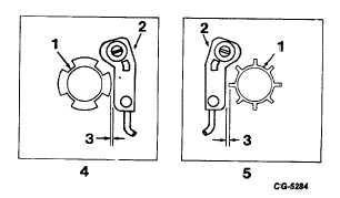
Fig. 49 Trigger Wheel-to-Sensor Air Gap
1. Trigger Wheel
4. 4 Cylinder Engine
2. Sensor
5. 8 Cylinder Engine
3. Air Gap
CGES-145-U Page 24
PRINTED IN UNITED STATES OF AMERICA
|