|
| |
ENGINE DIVISION SERVICE MANUAL
TM 5-4210-230-14&P-1
MECHANICAL ADVANCE SYSTEM SERVICE
Mechanical advance system components are not provided for
service individually. However, it is recommended that the
mechanical advance system be disassembled for inspection
and lubrication, as outlined below, at the time of distributor
overhaul.
Disassembly
(Refer to Figure 37).
IMPORTANT
Mark Advance weights, weight pivot pins and
trigger wheel assembly to assure reassembly in
the same positions.
1.
Remove felt wick.
2.
Remove trigger wheel assembly retainer from
distributor shaft using hooked extractor tool.
NOTE: Do not remove trigger wheel from the
trigger wheel assembly, Figure 37.
3.
Slide trigger wheel assembly from distributor shaft.
4.
Remove primary and secondary advance weight
springs.
5.
Remove advance weights and thrust washer.
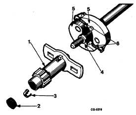
Fig. 37 Mechanical Advance System Components
1. Trigger wheel assembly
4. Thrust washer
2. Felt wick
5. Weights
3. Retainer
6. Springs
Inspect mechanical advance components. If wear or
damage is found, replace distributor shaft assembly.
Reassembly
1.
Lubricate advance weight bushings and pivot pins
with a light film of premium quality grease (Mobile
No. 532 or equivalent). Install weights on pivot pins.
2.
Install advance springs.
3.
Make sure advance weights pivot freely on pins.
4.
Lubricate trigger wheel assembly pilot surface of
distributor
shaft
with
premium
quality
grease.
Grooves in pilot diameter should be filled with
lubricant. Lands between grooves should have only
a thin film of lubricant.
5.
Apply a light coat of premium quality grease to thrust
washer and position thrust washer on distributor
shaft.
6.
Position trigger wheel assembly on pilot surface of
distributor shaft. Align slots in trigger wheel yoke with
pins on advance weights and push trigger wheel
assembly into position.
7.
Install trigger wheel assembly retainer. If necessary
bend arms of retainer to assure that retainer grips
slow in distributor shaft.
8.
Install felt wick.
9.
Make sure mechanical advance mechanism operates
freely.
TACHOMETER DRIVE SERVICE
Tachometer Drive Gear and Bearing Replacement
Tachometer drive gear and bearing (Figure 38) can
be replaced by following the procedure outlined below.
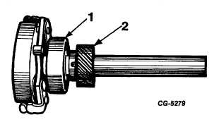
Fig. 38 Tachometer Drive Gear and Bearing
1. Bearing
2. Tachometer drive gear
CGES-145-U Page 17
PRINTED IN UNITED STATES OF AMERICA
|