|
| |
ENGINE DIVISION SERVICE MANUAL
TM 5-4210-230-14&P-1
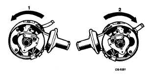
Notice that sensor mounting plate configuration and
vacuum diaphragm location varies between distributors with
right hand (clockwise) rotation and those with left hand
(counterclockwise) rotation as shown in (Figure 10).
Fig. 10 Illustrating Vacuum Diaphragm Location and Distributor
Rotation
1. Counterclockwise rotation
2. Clockwise rotation
1.
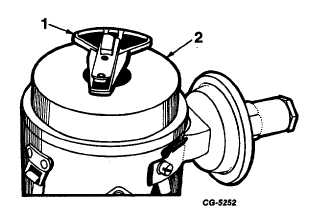
Remove rotor and dielectric shield ("dust cover")
(Figure 11)
Fig. 11 Distributor Rotor and dielectric Shield (Dust Cover).
1.
Rotor
2.
Dielectric Shield (Dust Cover)
2.
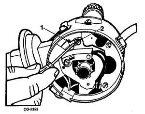
Remove vacuum advance diaphragm rod retaining "E"
clip (Figure 12) and flat washer (where used).
Fig. 12 Removing Diaphragm Rod Retainer
1. Diaphragm Rod
2. Retaining "E" Ring
3.
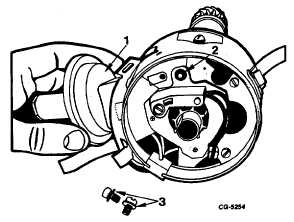
Remove vacuum advance diaphragm mounting screws
and remove diaphragm assembly from distributor
housing (Figure 13). Remove felt washer from
diaphragm rod pin on sensor advance plate. (Figure
13).
Fig. 13 Removing Vacuum Advance Diaphragm Assembly.
1. Diaphragm Assembly
2. Felt Washer
3. Retaining Screws
4.
Remove electronic control unit (circuit board, sensor
and plate assembly) as follows:
CGES-145-U Page 9
PRINTED IN UNITED STATES OF AMERICA
|


