|
| |
TRUCK SERVICE MANUAL
TM 5-4210-230-14&P-1
BODIES AND CABS
CHAPTER II WINDSHIELD WIPER (AIR)
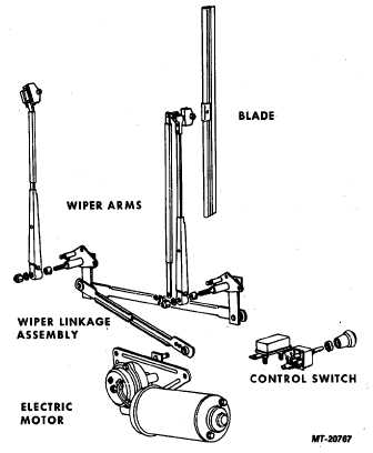
Fig. 1 Air Windshield Wiper Components
DESCRIPTION
Where air brake equipment is specified for S-Series
Trucks, an air operated windshield wiper is also available
optionally. This air wiper system (Fig. 1) consists of an air
operated wiper motor, an instrument panel mounted control
valve and the same wiper linkage as used for the standard
windshield wiper system.
OPERATION
The air wipers operate in a similar manner to
conventional wipers so long as air pressure is supplied to the
air wiper system. However, to start wipers, control knob must
be pulled out. Wiper speed is then controlled by turning knob
clockwise or counterclockwise. Push knob in to stop wiper
motor. Reciprocating action of wiper arms results from
reciprocating action of drive lever on air wiper motor.
REMOVAL
Linkage
Air wiper linkage removal procedure is the same as
required for the standard electric wiper as covered in Chapter
I.
Air Motor
1.
Disconnect air lines from fittings on air motor.
2.
If wiper linkage has not previously been disconnected
from air motor, reach into cowl fresh air intake
chamber and unfasten clip from air motor drive lever.
3.
Remove wiper motor bracket mounting screws and
detach air motor assembly from cowl.
Control Valve
1.
Remove control valve knob from valve on instrument
panel. A small hex key wrench can be used to loosen
knob set screws.
2.
Remove mounting screws and detach panel to right of
control valve.
3.
Remove mounting nut from valve shaft and detach
wiper control valve from instrument panel.
4.
Disconnect air hose from control valve and remove
control valve unit.
INSTALLATION
Air wiper components are installed in the reverse order
of disassembly procedure. When returning wiper arms to
serrated ends of drive shafts, the following steps should be
observed to assure correct wiper blade positioning on
windshield.
1.
With vehicle air pressure at 620 kPa (90 psi) note that
wiper motor moves wiper blade to "Park" position when
control knob is pushed in. Wiper blades should be 25
mm (approx. 1 inch) up from bottom of windshield.
2.
If adjustment is necessary, remove wiper serrated nut
from wiper arm and reposition arm and nut to specified
wiper position. Adjust each wiper arm individually.
Moving arm or nut one serration is equal to
approximately five (5) degrees blade travel.
CTS-2732 Page 1
PRINTED IN UNITED STATES OF AMERICA
|