|
| |
TRUCK SERVICE MANUAL
TM 5-4210-230-14&P-1
BODIES AND CABS
Legend for Figure 6
Key
Description
1
Hinge, Cab Door
2
Door, Assembly, Cab
3
Seal, Door Glass
4
Seal, Door
5
Seal, Door Glass Rear Channel
6
Glass, Door Window
7
Guide, Door Window
8
Channel, Rear Run
9
Knob, Door Lock
10
Rod, Lock Knob to Latch
11
Handle, Assembly Door Outer
12
Latch, Assembly, Door
13
Rod, Remote Control to Latch
14
Rod, Lock Cylinder to Latch
Key
Description
15
Control Assembly, Remote
16
Retainer, Door Trim
17
Panel, Door (Custom Trim)
18
Arm Rest
19
Washer, Door Trim
20
Handle, Window Regulator
21
Handle, Door Remote
22
Pocket, Manifest (Custom Trim)
23
Retainer, Access Door
24
Pocket, Manifest (Standard Trim)
25
Regulator, Assembly, Window
26
Seal Door Glass Front Channel
27
Vent, Assembly Window Glass
Fig. 7 Door and Hinge Details
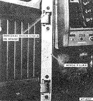
DOOR HINGES
An integral door check (Fig. 7) is included in the
upper hinge used with this door. If door is removed, upper
and lower hinges should not be interchanged. There is no
disassembly of hinges since they are serviced as a complete
unit. It should also be noted that hinge mounting holes are
elongated to provide adjustment for positioning cab door in
door opening.
Fig. 8. Removing Door From Cab
Remove
1.
Remove door hardware and trim as covered
previously.
2.
Using a rope sling (or padded chain) through window
opening, attach sling to overhead lift and support
door.
3.
Remove four button plugs for access to hinge bolts.
4.
Remove the four flange head hinge bolts and lift door
assembly from hinges (Fig. 8).
5.
Place door on saw horses or similar support. Protect
paint from scratches.
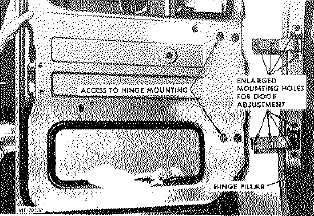
6.
To simplify door adjustment on reassembly, mark
hinge position on hinge pillar with scratch awl before
loosening hinges. Remove the three flange head
bolts and detach door hinge from hinge pillar (Fig.
9).
CTS-2714 Page 9
PRINTED IN UNITED STATES OF AMERICA
|