|
| |
TRUCK SERVICE MANUAL
TM 5-4210-230-14&P-1
BODIES AND CABS
4.
Remove plug from outlet opening of filter dehydrator.
Remove cap or tape from outlet hose. Lubricate
threads with refrigerant oil and connect outlet hose to
filter-dehydrator.
IMPORTANT
To avoid contamination, do not uncover filter-dehydrator
openings longer than necessary to make connections.
5.
Evacuate and charge air conditioning system as
outlined under SERVICE OPERATIONS.
HEATER CORE
Removal:
1.
Raise hood and fender assembly.
2.
Drain engine cooling system.
3.
Remove cover from right side of instrument panel.
4.
Remove cover from heater/evaporator unit.
5.
Loosen hose clamps at heater core.
6.
Open blend air door.
7.
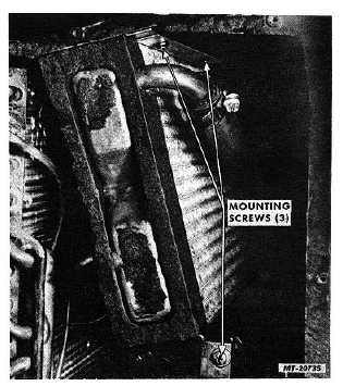
Remove heater core mounting screws (Fig. 51).
8.
Disconnect hoses from heater core and pull core
outward (toward rear of vehicle) to remove.
9.
Remove gaskets from ends of heater core.
10.
Inspect hoses and gaskets and replace if damaged
or deteriorated.
Installation:
1.
Position gaskets on ends of heater core.
2.
Open blend air door.
3.
Position heater core into housing. Align slot in
heater core frame with rivet at front of housing and
push heater core into position
4.
Install heater core mounting screws.
5.
Connect hoses to heater core and tighten hose
clamps.
6.
Refill engine cooling system.
Fig. 51 Heater Core Mounting Screws
7.
Set heater (HTR) control lever at "HOT". Operate
engine. Check for coolant leaks and coolant flow
through heater core.
8.
Install
covers
on
heater/evaporator
unit
and
instrument panel.
9.
Lower hood and fender assembly.
HIGH SPEED AND LOW PRESSURE SWITCH
RELAYS
Relays are mounted on defroster duct and are
located in front of instrument panel and above blower motor.
Removal:
1.
Disconnect battery cable.
2.
Remove cover from right side of instrument panel.
3.
If relays are accessible, proceed to Step 4.
If relays cannot be reached, remove radio/ ash tray
panel, as follows, to gain access to relays.
a.
Remove radio/ash tray panel mounting screws and
pull panel outward.
CTS-2731 Page 35
PRINTED IN UNITED STATES OF AMERICA
|