|
| |
TRUCK SERVICE MANUAL
TM 5-4210-230-14&P-1
BODIES AND CABS
Vehicles with air conditioning have a powerful
permanent magnet type blower motor which utilizes a vent
tube for efficient motor cooling. On vehicles with heater only,
a smaller permanent magnet type motor is used.
A resistor assembly is used in the blower motor
circuit to provide three speed settings, "LOW", "MEDIUM" and
"HIGH". The resistors are located in the blower air stream to
prevent overheating.
On vehicles with air conditioning, a high speed relay
is used to accommodate the high current demand of the
larger blower motor. This avoids a high current flow through
the switch during high speed operation. When the blower is
operated on "LOW" or "MEDIUM" speed, current flows from
terminal "2" of the resistor assembly to terminal 12" of the
relay and out through terminal "1" of the relay to the motor.
When the switch is turned to "HIGH", relay terminal "4" is
energized, allowing current to flow from a 30 amp fuse to
terminal "3" of the relay and out through terminal "1" to the
motor. (See wiring circuit diagram, Fig. 17.)
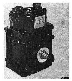
Refrigerant Compressor
The compressor (Fig. 6) is a two-cylinder recipro-
cating type unit. It is mounted on the engine and belt driven
through
an
electromagnetic
clutch
mounted
on
the
compressor crankshaft. The compressor compresses and
superheats refrigerant gas received from the evaporator and
propels the refrigerant through the system.
Fig. 6 Refrigerant Compressor
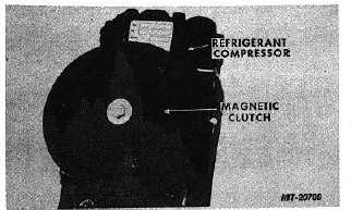
Magnetic Clutch
The electro-magnetic clutch (Fig. 7) is used to
couple and uncouple the compressor from the V-belt drive. It
cycles the compressor "ON" or "OFF" in response to signals
from the thermostatic temperature control switch. When
thermostatic switch demands cooling, the clutch is engaged
setting the compressor in motion. When cab interior
temperature satisfies thermostatic switch, the clutch field coil
is de-energized releasing clutch plate from pulley, ceasing
compressor operation. Use of a cycling clutch system
reduces
engine
load,
maximizes
compressor
life
and
enhances fuel economy.
Fig. 7 Magnetic Clutch
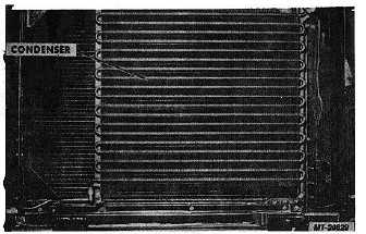
Fig. 8 Refrigerant Condenser
Condenser
The refrigerant condenser (Fig. 8) is mounted at the
front of the vehicle between engine cooling system radiator
and grille. As refrigerant passes through the condenser, heat
that was picked up in the evaporator and during compression
is given up to the cooler air flowing through the condenser
fins. Refrigerant condenses from a high pressure gas to a
high pressure liquid.
CTS-2731 Page 6
PRINTED IN UNITED STATES OF AMERICA
|