|
| |
TRUCK SERVICE MANUAL
TM 5-4210-230-14&P-1
AXLE-FRONT
OPERATION
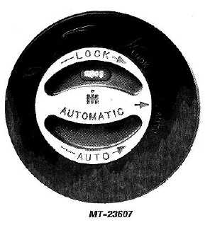
The automatic hub, when set in the "AUTO" position,
automatically locks the front wheel and axle shaft together the
moment torque is applied to the front axle. The hub controls,
therefore, do not require changing regardless of whether the
vehicle is being operated in two or four-wheel drive. It is
necessary, however, to set the control in the "LOCK" position
when engine braking control is required (down steep hills, on
ice, etc.).
Fig. 2. Dial Control
DO NOT DRIVE unless controls on both hubs are set properly
and both are set the same!
For the first 320 km (200 miles) operate your new vehicle with
the automatic hubs in "LOCK" position to assist in initial
break-in of the front driving axle. Place transfer case control
in 2-wheel drive position.
Always shift transfer case to 2WH before attempting to
disengage the locking hubs.
This will help to eliminate drive line wrap up which results
from 4W drive operation. Also, this will allow automatic hub
to disengage by rotating the control dial.
IMPORTANT
Torque wind up may be relieved by turning
hard right or left and backing up a short
distance while pushing the transfer case lever
into 2WD.
LUBRICATION
When reassembling the locking hub, lubricate as follows:
Lubricate dial, seals, splines, threads, rollers, cage, centering
spring and body with IH 251 HEP grease.
Fill
area
between
and
around
friction
shoes
with
approximately two tablespoons of grease. All remaining
surfaces require only a light coating. Excessive grease can
create malfunction of hub.
SERVICING
This locking hub is serviced in two major assemblies, namely,
a clutch half and body half. Since all individual components
are not provided, refer to the Scout Parts Catalog when
ordering.
To disassemble:
1.
Bend lock tabs out of way.
2.
Remove six (6) bolts.
3.
Remove cap assy.
4.
Remove snap ring from axle shaft.
5.
Remove body assy.
To reassemble:
1.
Clean gasket surface.
2.
Reverse disassembly procedure using new gasket
and lock tabs.
TORQUE SPECIFICATION
Torque hub assembly mounting bolts to 32-40 ft. Ibs. 43-54
N-m.
CTS-2785 CHAPTER I Page 3
PRINTED IN UNITED STATES OF AMERICA
|