|
| |
TRUCK SERVICE MANUAL
TM 5-4210-230-14&P-1
AXLES-FRONT
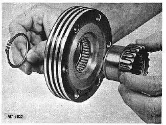
Fig. 7. Removing Axle Shaft Hub
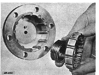
Fig. 8. Removing Clutch Ring and Screw
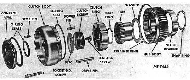
Fig. 9. Manual Type Locking Hub with Socket Head Mounting Screw (Exploded View)
Clutch Body (Manual Type)
Using a small chisel, remove the staked over metal retaining
the flat head screw (7). NOTE: Be careful when removing this
material not to damage the clutch screw (8). Remove the
screw (7). Lift out clutch screw (8) and clutch ring (6). Clutch
ring (6) may be separated from clutch screw (8) by
unscrewing it, Fig. 8. Turn clutch body face down to take out
the drive pins (11).
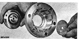
Remove disc (9) from bottom center of clutch body (13).
Place thumb inside clutch body (13) on center of control
assembly (16) and push outward, Fig. 10. Remove O-ring
seal(l0)and
outer
oil
seal
(17)
from
control
dial (16). Dowel pin (20) may be lifted out of control dial (16).
The poppet ball and spring located in the control dial cannot
be serviced therefore, if damaged, the-control assembly (16)
must be replaced.
Fig. 10 Removing Control Assembly and Disc from Clutch
Body
CTS-2209-H Page 5
PRINTED IN UNITED STATES OF AMERICA
|