|
| |
TRUCK SERVICE MANUAL
TM 5-4210-230-14&P-1
AXLES-FRONT
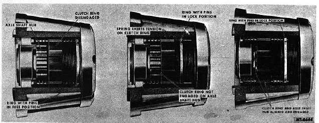
Fig. 5. Three Stage Operation of Spring Loaded Manual Locking Hub
A later version of the manual type locking chub is the spring-
loaded type, Fig. 5, which is designed to aid in the
engagement or disengagement of the front wheels with the
axles. These hubs overcome the need of moving the vehicle
slightly when the clutch ring does not mesh properly with the
axle shaft hub.
This spring in these new hubs permits the control to be
positioned in the desired location, and the slight movement of
the vehicle will allow the clutch ring to move into "LOCK" or
"FREE" position as selected on the control.
Lock- O- Matic Type
The Lock-O-Matic hub, when set in the "FREE" position,
automatically locks the front wheel and axle shaft together the
moment torque is applied to the front axle. The hub controls,
therefore, do not require changing regardless of whether the
vehicle is being operated in two or four-wheel drive. It is
necessary, however, to set the control in the "LOCK" position
when engine braking control is required (down steep hills, on
ice, etc. ).
OPERATION
Engaging Locking Hubs
To engage locking hubs, turn brass controls (one on each
hub) clockwise to "LOCK" position, Figs. 1 and 3. Arrow in
center of controls must point directly at dot located on rim of
hub. You can feel the brass control "seat" itself when it is
properly positioned. If the arrow does not point directly at the
dot, the control will not seat itself. Thus, the gears will not
completely engage, and the pressure may force off the end of
the hub. This is only true of hubs that are not spring loaded.
Hubs that are spring loaded allow the control to be positioned
in the engaged location, but engagement of the clutch ring on
the axle shaft hub is not accomplished due to misalignment of
components. Then when the vehicle is moved slightly, the
spring-loaded clutch ring will engage with the axle shaft hub,
Fig. 5 Right.
Disengaging Locking Hubs
To
disengage
locking
hubs,
turn
brass
controls
counterclockwise to "FREE" position, Figs. 2 and 4. Here,
again, the arrow must point directly at the dot on the rim,
otherwise the gears may rake against each other.
The hub on the left side in Fig. 5 illustrates the spring-loaded
type locking hub in the "FREE" position.
When controls are properly positioned, gears are completely
engaged or disengaged and units will not be damaged.
The following CAUTION hints may prevent damage to the
locking hubs:
1.
Use fingers only to turn controls. If control's do not
move freely with your fingers, move vehicle slightly in
either direction in two-wheel drive, standard gear
range. If hubs do not now turn freely, look for
external damage or dirt around brass controls. DO
NOT force controls with tools.
2.
DO NOT drive vehicle unless controls on both hubs
are properly positioned and both are set the same.
CTS-2209 Page 3
PRINTED IN UNITED STATES OF AMERICA
|