|
| |
TM 5-4210-230-14&P-1
TRUCK SERVICE MANUAL
STEERING
2.
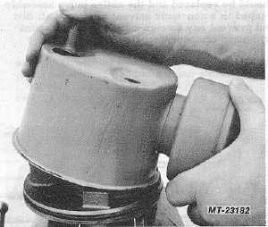
Remove stud and union 11/16 box (stud) and l--inch
deep well socket (union), (Fig. 1). Tip pump to remove
flow-control valve and spring. (Fig. 2)
3.
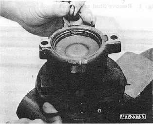
Remove reservoir. Reservoir may be removed from
,housing by rocking it back and forth to unseat the "O"
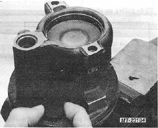
ring (Fig. 3). Remove housing and union "0'" rings and
discard (Fig. 4).
Fig. 3 Remove Reservoir
Fig. 4 Remove Housing and Union "O" Rings
4.
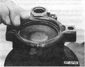
Remove magnet from housing and clean with solvent
(Fig. 5).
Fig. 5 Remove Magnet
5.
Rotate retaining ring with blunt-nosed punch until the
ring opening is approximately 6 mm (1/4 in.) from
knock-out hole in pump housing (Fig. 6).
6.
Insert needle-nosed punch into knock-out hole and tap
with hammer until ring is forced away from housing.
Insert screwdriver beneath retaining ring and pry away
the full diameter until the ring is free (Fig. 7).
Fig. 6 Rotate Retaining Ring
CTS-2296R Chapter 3, Page 4
PRINTED IN UNITED STATES OF AMERICA
|