|
| |
TM5-4210-229-14&P
6-15
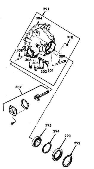
TRANSMISSION REPAIR (Continued)
(b) Using output shaft oil seal and dust shield
remover, remove the dust shield (292).
(c) Using remover again, remove the oil seal
(293) from the rear cover (291).
(d) After removing the beveled snapring (294) that
retains the rear output shaft bearing (295)
remove the bearing(295). Use a soft drift and
drive against the bearing outer race.
(e) Place first clutch spring compressor on the
piston spring retainer (296). Install spring
compressor base. Compress the spring
retainer (296) and remove the snapring (297).
Carefully release the spring compressor and
remove it.
(f)
Remove
the
spring
retainer
(296)
and
twenty-six springs (298).
(g) Remove the clutch piston (299). Re-move the
inner sealring (300) and outer sealrings (301)
from the piston.
(h) Remove plug (301), sealring (302), and oil
filter (303) from the cover (304). Remove
plugs (305) and (306).
(i)
The governor (307) may be disassembled for
cleaning and inspection. Do not disassemble
the governor unless the kit consisting of two
governor weight pins and the cover gasket is
available.
(j)
Follow the directions furnished with the kit to
disassemble the governor (307).
(k) If replacement is necessary, remove the
governor support pin (308) using governor
support pin remover.
(l)
Remove tube (309) and plug (310) only if
replacement is necessary.
(2)
Assembly
(a) If removed, install the governor support pin
(308).
Use
governor
support
pin installer to install the governor support
pin (308).
NOTE
Accuracy of location and concentricity with the
governor bore is of the utmost importance. The pin
must be installed 5.886 to 5.896 inch (149.50 to 149.76
mm) from the outside edge of rear cover bore to
closest edge of pin.
(b)
Install drain tube (309) into rear cover. Press
rubber tube (309) into cover (304) until it is
0.020-0.150 inch (0.51-3.81 mm) below the
surface in the cover.
6-80
|