|
| |
TM5-4210-229-14&P
6-15.
TRANSMISSION REPAIR (Continued).
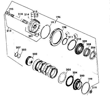
(h) Hold the fourth clutch driving hub (200)
firmly against the snapring and, using
forward clutch clearance gauge check the
clearance between the fourth clutch driving
hub (200) and the internal-splined clutch
plate (204). The prescribed clearance for
the forward clutch is 0.079-0.130 inch
(2.01-3.30
mm).
When
clearance
is
achieved, the first step of clearance gauge
will fit between the hub and plate; the
second step will not.
(i) If the clearance is excessive (second step
of gauge fits), replace the thinner clutch
plates with new plates. If the clearance is
still excessive after all ten plates and
fourth clutch drive hub (200) have been
replaced, a thicker piston (209) is required.
(j) If the clearance is insufficient (first step of
gauge will not fit), a thinner piston (209) is
required.
(k) Remove the snapring (199) that retains the
fourth clutch driving hub (200) and remove
the hub (200). Remove the forward clutch
plates (204 and 205).
CAUTION
If either piston sealring (210 or 211) is
installed incorrectly, the forward clutch will
not operate properly.
(I) Lubricate and install the piston sealrings
(210 and 211) into their grooves in the
housing hub (201) and piston (209). Make
sure the sealring lips face toward the oil
pressure side of the piston. Install the
piston (209) into the housing.
(m) Place the clutch housing and shaft
assembly, and assembled piston on a
press bed. Install the piston return spring
(208) and spring retainer (206) and position
the snapring (207) on the hub. Using
compressor
tool,
depress
the
spring
retainer (206) sufficiently to install the
snapring (207) into its groove in the
housing hub.
6-68
|