|
| |
TM5-4210-229-14&P
6-15.
TRANSMISSION REPAIR (Continued).
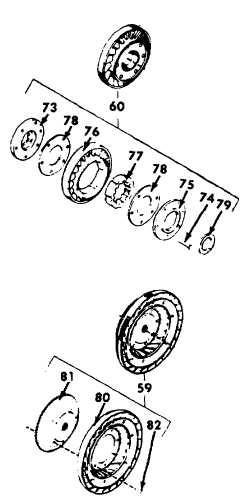
(m) Place the stator assembly (60) on fixture
stand.
Install
staking
tool
into
the
fixturehead and tighten the thumb screw
finger tight.
(n) Apply approximately 800 pound (3629 kg)
load to swage each rivet head. Swage the
second rivet 180 degrees from the first.
Locate the third rivet, 60 degrees from the
second and swage it. Locate the fourth
rivet 180 degrees from the third, etc., until
all rivets are swaged.
(o) Remove the retaining bolt, top plate, base
plate and staking tool. Install new needle
bearing (79) referring to paragraphs a. (2)
(o) through a. (2) (r) above.
(4) Converter turbine repair.
NOTE
Do not disassemble the turbine unless
the turbine hub must be replaced. If the
converter turbine is damaged, replace
the assembly (59).
A hydraulic press having a minimum
capacity of ten tons (9,070 kg), an
adjustable press bed with a 25 inch (635
mm) opening and a pressure gauge to
assist in determining the rivet swaging
load, are required to repair the turbine
assembly (59).
(a) Punch alignment marks on the turbine (80)
and turbine hub (81) to show their
relationship.
(b) Place base plate on a work table, rivet hole
side up.
(c) Place converter turbine assembly (59)
front side upward (turbine vanes down), on
top of the base plate. Align the eight rivets
(82) in the hub to the holes in the base
plate.
(d) Place guide plate on top of converter
turbine assembly (59). Centrally locate
each rivet (82) in the guide plate holes.
(e) Install the 1/2-13x3-1/2 inch clamping bolt
to retain the guide plate, turbine and base
plate together. Torque the bolt 50 ft-lb (68
N.m).
(f) Place the turbine assembly and fixture in
the drill press.
CAUTION
Do not use a hammer to remove the
rivets, damage to turbine assembly may
result.
(g) Place drill bushing into guide plate. Using a
1/4 inch drill, drill approximately 3/16 inch
deep into the rivet.
6-52
|