|
| |
TM5-4210-229-14&P
6-15. TRANSMISSION REPAIR (Continued).
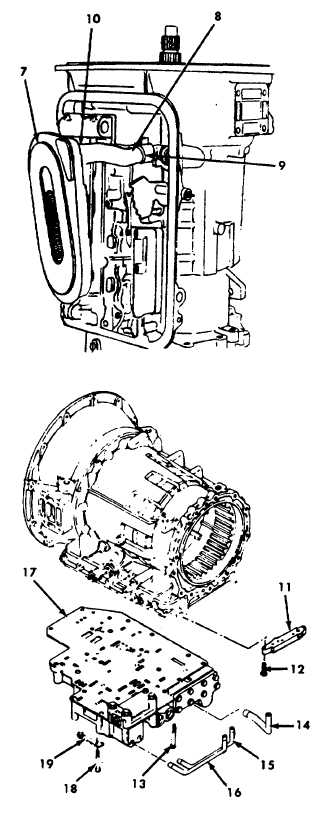
e. Control valve assembly removal.
(1) Using a rubber band, or a suitable sub-
stitute, secure the range selector valve to a
pad on the control valve body (17). Remove
the bolt that attaches the detent spring and
roller assembly (18). Remove the detent
spring and roller assembly (18). Loosen two
bolts at the top of the control valve body
(17) to act as support bolts. Remove the
remaining bolts that attach the control
valve body (17) to the transmission hous-
ing.
(2) Hold the control valve body assembly (17)
firmly and remove the two remaining bolts.
Remove the control valve in a downward
and outward movement to clear the actu-
ator pin from the housing bore.
f. Oil pump and front support removal.
(1) Remove twelve bolts and twelve rubber-
covered washers that retain the oil pump
and front support assembly. Discard rub-
ber-covered washers.
(2) Install front support lifter onto the conver-
ter ground sleeve. Be sure the lifter is se-
cure before removing the front support.
When lifting an object, make sure the hoist is
fastened securely. Be sure the item being
lifted does not exceed the capacity of the
lifting device.
CAUTION
The pump and front support assembly is
fitted to the transmission housing with very
little clearance. It may bind in the housing if
the housing is cold. Heat the housing
slightly, if necessary. Do not use a torch to
heat the housing. A sun lamp or a current of
warm air will be sufficient. If the pump and
support assembly starts upward and then
binds, tap it downward and lift again.
6-45
|


