|
| |
TM5-4210-229-14&P
6-12. PISTON AND CONNECTING ROD MAINTENANCE (Continued).
Compressed air used for cleaning or drying
can create airborne particles that may enter
the eyes. Pressure shall not exceed 30 psi
(206 kPa). Wearing of goggles is required to
avoid injury to personnel.
(3) Dry the sleeves with compressed air.
(4) Clean and flush out the water jacket in the
crankcase.
(5) Measure the I.D. of the sleeve with an inside
micrometer or bore gauge from the top and
bottom of the sleeve where it is subjected to
piston and ring travel, and the O-ring area.
(a) Take measurements at right angles to
determine if the sleeve is out of round
or excessively tapered.
(b) Maximum permissible diameter sleeve
wear, at top of ring travel, before re-
placement is 0.004 in (0.10 mm).
(c) If sleeve does not meet specifications,
it must be replaced with a new sleeve
(and piston).
(6) Inspect the sleeve for scuffing or scoring.
Replace sleeve (and piston) if this condition
is found.
CAUTION
Do not hone the cylinder sleeves.
(7) Inspect counterbore for burrs or fractures,
replace if evident.
INSTALLATION
a. Connecting rods, pistons, and rings assembly.
(1) Install new connecting rod piston pin bush-
ing using a suitable arbor press. Bore or
hone the new bushing to 1.6256 to
1.6258 in. (41.2902 to 41.2953 mm) after
assembly.
(2) Generously coat the piston bore and piston
with molykote (Appendix D, Item 35).
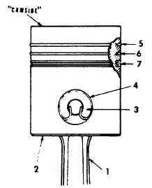
(3) Insert the pin end of the connecting rod (1)
into the piston (2) aligning bored holes of
the rod and piston (the short side of the
split on the crank end of the rod is to be
toward the side of the piston marked cam-
side).
(4) Align the bushing in the rod with the piston
pin holes in the piston and push the piston
pin (3) completely into position. (Pin is a
loose fit at 70° F (21° C).)
(5) Squeeze the pronged ends of the piston pin
retainer rings (4) and install a ring in the
groove at each end of the piston to secure
- the piston pin.
(6) Using a piston ring expander, install the
rings into the grooves of the pistons.
(a) The compression rings (groove num-
bers 5 and 6) must be installed as direc-
ted by the word top, up or pip, mark
stamped on the edge. The tappered
face second compression rings must
have the witness mark (shiny part) to-
wards the bottom of the piston.
(b) The oil-regulating ring (groove number
7) can be installed with either face up.
6-33
|

