|
| |
TM5-4210-229-14&P
6-10. TIMING AND GEAR TRAIN MAINTENANCE (Continued).
b. Blow dry parts with compressed air.
c. Visually inspect all gears for wear or damaged
teeth. Replace any with evidence of damage.
d. Visually inspect bearings, spacer, and stub shaft
for wear or damage.
INSTALLATION
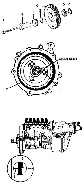
a. Idler gear installation.
(1) Assemble spacer (1), bearing (2), spacer
(3), bearing (4), and stub shaft (5) to idler
gear (6).
(2) Install assembled parts with the timing marks
facing out. Be sure the rear spacer (1) is in
position. A small amount of grease (Appen-
dix D, Item 21) will aid in holding the spacer.
(3) Install and torque the retaining bolt (7) to
85 ft-lbs (115 N.m).
b. Injection pump gear installation.
CAUTION
Be sure that engine crankshaft timing is set
at specified static timing prior to going any
further.
(1) Using drive gear bolts and washers (1),
loosely install injection pump drive gear (2)
to injection pump meshing it with idler gear.
Make sure drive gear is positioned in gear
slots so it allows for adjustments.
(2) Align timing pointer (3) with timing mark
(4) by rotating injection pump clockwise (as
viewed from drive gear end.)
(3) Holding the pump shaft with a socket wrench,
torque drive gear bolts to 35 ft-lb (47 N.m).
(4) Rotate engine crankshaft counterclockwise
until pump timing pointer and timing mark
align.
(5) Observe engine to injection pump timing on
crankshaft pulley. Timing sould be 23° ñ 1°.
c. Install camshaft and gear (paragraph 6-9).
6-22
|

