|
| |
TM5-4210-229-14&P
5-21. AIR DRYER REPAIR (Continued).
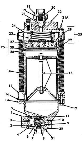
q.
Position filter assembly into body (14) with large
end down. The filter must set on packing ring
(26).
r.
Install heavy spring (23) with larger diameter coil
against top of filter assembly.
s.
Position new gasket (24) on body.
t.
Position top cap (22) and spring (39) so that the
small diameter coil on spring fits groove in top
cap.
u.
Compress spring (39) and install four 3/8 inch cap
screws (21) into body (14). Each of these four
screws should be engaged at least three full turns
before load on cap is removed. Cap screws
should be equally spaced. Then thread remaining
screws into place.
v.
Tighten all top cap bolts (21) alternately and
evenly to 15 ft-lb (20.4 N.m).
w.
Position new check valve spindle (2 1) in top cap
(22) with tapered end down.
x.
Install spring (20) in check valve spindle (21).
y.
Position new copper gaskets (1 9) in nut (18) and
rub a small quantity of grease (Appendix D, Item
21) on the gaskets to help them keep their
position in the top nut (18).
z.
Thread nut (18) on top cap (22) and torque to 60
ft-lb (81 N.m). Top nut (18) is not included in
check valve replacement kit.
aa. Install new gaskets (16) and (17).
bb. Align bolt holes and position assembly against
bottom gasket surface of body (14).
cc. Insert eight cap screws (12) to attach bottom cap
(13) to body (14) and deflector assembly (15).
Tighten alternately and evenly to 15 ft-lb (20.3
N.m).
5-53
|