|
| |
TM5-4210-229-14&P
4-201.
FRONT AXLE SHAFT AND JOINT ASSEMBLY REPLACEMENT (Continued).
f.
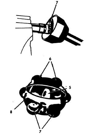
Tilt inner race (5) in outer race (6) until one ball
(7) can be removed, continue this procedure
until all balls (7) are removed. A soft faced
hammer may be used to aid inner race (5)
movement.
g.
Roll universal joint cage (8) at a right angle to
universal joint outer race bell (6) with the two
elongated openings in cage (8) aligned with
opposite teeth of outer race bell (6). Lift cage
(8) and inner race (5) from outer race bell (6).
h.
Inspect axle shaft and universal joint assembly
for seizure, broken or chipped balls, broken
splines or other damage.
i.
Inspect spindle bushing for out of round
condition caused by wear or corrosion, scoring
or roughness in spots.
j.
Inspect axle shaft oil seal for evidence of wear
or damage.
k.
Inspect for evidence of wear due to improper
drive flange shim size. Wear on the interior
surface of ball end of axle housing and on edge
of ball joint bell housing indicates the use of too
thin a shim, allowing contact between the two.
If shim is too thick, the spindle bushing will
show excessive wear.
INSTALLATION
a.
Assemble inner race and cage by indexing
notched tooth of inner race with elongated
opening in cage and rolling inner race into cage.
b.
Align elongated openings of cage with opposite
teeth of outer race bell and lower inner race and
cage assembly into outer race bell.
c.
Tilt-inner race in outer race until one ball can be
inserted, continue this procedure until all balls
are inserted. Pre-lubrication of components and
a soft faced hammer may be used to aid inner
race movement.
d.
Install new lock ring (6) on axle shaft end and
place axle shaft (3) in a vise equipped with soft
jaws.
e.
Place universal joint (1) on top of axle shaft
index end (4) of axle shaft in splined inner
race. Tap end of universal joint shaft with a
soft faced hammer to collapse lock ring,
securing assembly.
f.
Pack
universal
joint
bell
with
lubricant
(Appendix D, Item 21).
When installing axle shaft and universal joint
assembly, care should be taken not to damage axle
shaft oil seal.
Install axle shaft (3) and universal joint assembly (1) in
axle housing indexing splined end of axle shaft with
side gear of center unit (2).
g.
Install steering knuckle and arm.
4-219
|

