|
| |
TM5-4210-229-14&P
4-189. STEERING KNUCKLE AND ARM REPLACEMENT (CONTINUED)
NOTE
It is not necessary to remove the upper trunnion pin
upon trunnion housing disassembly.
INSTALLATION
a.
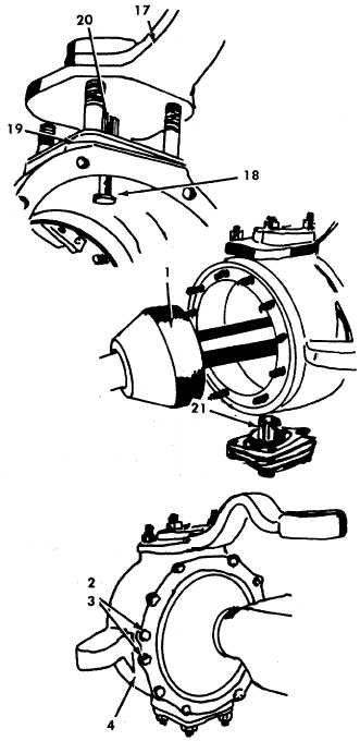
Using original shim pack (19) install upper trunnion
cap (17).Torque retaining nuts to 60-70 ft-lb (81-95
N.m). Install tapered dowels (16) before installing
lockwasher (13) and retaining nuts (12). Torque
retaining nuts to 60-70 ft-lb (81-95 N.m).
b.
Lubricate trunnion bearings thoroughly using grease
(Appendix D, Item 20). Place a trunnion bearing on
upper trunnion bearing cup of axle housing end.
Lower trunnion housing (11) into place on axle
housing end indexing upper trunnion pin (18) with
upper trunnion bearing (20).
c.
Place lower trunnion bearing (21) in bottom of
trunnion housing (11) and align with lower bearing
cap. Using original shim pack (15) install lower
trunnion cap (14). Torque retaining nuts to 60-70
ft-lb (81-95 N.m).
d.
Check trunnion bearing adjustment by placing a
torque wrench on trunnion cap (11) or steering arm
retaining nut (12) and swinging trunnion housing
(11). Torque should be 8-15 ft-lb (11-20 N.m). To
increase torque, remove shims (15) or (19) to
decrease torque, add shims.
e.
Install gasket (10), flange (9), steering ball felt (8),
seal with spring (7), split retainer ring (6) and
retaining ring halves (5) on rear of trunnion housing
(1).
f.
Install retaining half lockwashers (.3) and mounting
bolts (2). Torque mounting bolts to 10-15 ft-lb
(14-20 N.m).
g.
Install axle shaft and universal joint assembly (1) in
axle housing indexing splined end of axle shaftwith
side gear of center unit.
When installing axle shaft and universal joint assembly,
care should be taken not to damage axle shaft oil seal.
h.
Slide spindle over universal joint shaft and on
to
trunnion housing studs (paragraph 4-188).
i.
Install wheel bearings (paragraph 4-187,).
j.
Install hub/drum assembly (paragraph 4-186).
k.
Install service brakes (paragraph 4-169).
l.
Install tire rim assembly (paragraph 4-162).
4-205
|

