|
| |
TM 5-4210-229-14&P
4-115. HEATER/DEFROSTER CONTROL ASSEMBLY REPLACEMENT.
This task covers:
a. Removal
b. Installation
INITIAL SET-UP
Tools
General Mechanics Tool Kit
Materials/Parts
Control Assembly (150-90002-0)
General Safety Instructions
Engine OFF.
Transmission in (N) neutral.
Parking brake set.
Batteries disconnected.
REMOVAL
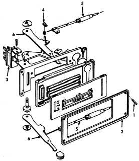
a. Remove four control assembly mounting
screws (1). Remove control assembly trim plate
(2). Pull control assembly outward.
b. Disconnect wiring harness connector from blower
switch (3).
c. Disconnect instrument panel lamp socket from
control assembly.
d. Remove retaining nuts (4) from the cable
assemblies (5).
e. Remove cable assemblies (5) from control levers
(6).
f. Remove control assembly.
INSTALLATION
a. Connect control cables (5) to control assembly levers (6).
(1) Cable with white mounting tab upper (HTR) lever.
(2) Cable with black mounting tab to lower (AIR OUTLET) lever.
(3) Install control cables (5) and cable retaining nuts (4).
b. Connect instrument panel lamp socket to control assembly.
c. Connect wiring harness connector to blower switch (3).
d. Position control assembly in instrument panel and install trim plate (2) and mounting screws (1).
e. Connect battery cables.
f. Check operation and adjustment of control cables.
4-127
|

