|
| |
TM 5-4210-229-14&P
4-108. CONTROL SWITCHES AND GAUGES REPLACEMENT.
This task covers:
a. Removal
b. Installation
INITIAL SET-UP
Tools
General Mechanics Tool Kit
Materials/Parts
Switches and Gauges as required
(Appendix E, Figure 75)
Equipment Condition
Para. Equipment Description
4-106 Cluster Assembly Removed
General Safety Instructions
Engine OFF.
Transmission in (N) neutral.
Parking brake set.
REMOVAL
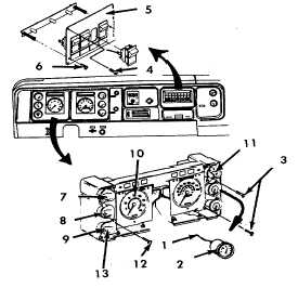
a. Air gauge removal.
NOTE
Air gauges are mounted to a common bracket and
are removed as an assembly from the cluster
assembly.
(1) Disconnect air lines (1) from fittings on rear
of air gauges (2).
(2) Remove two air gauge mounting assembly
screws (3) and remove gauge assembly.
b. Control switches removal.
(1) Remove four mounting screws (4) and
remove panel (5) from dash panel.
(2) Remove two screws (6) and remove circuit
board from the panel (5).
(3) Tag and remove wires from switches.
(4) Depress switch retainers and remove
switches.
c. Gauge removal.
NOTE
This procedure is typical for the following gauges:
WATER TEMPERATURE GAUGE, (7), OIL
PRESSURE GAUGE (8), VOLTMETER (9),
TACHOMETER (10), and FUEL GAUGE (11).
(1) Remove two mounting screws (12).
(2) Remove gauge (13).
INSTALLATION
a. Air gauge installation.
NOTE
Air gauges are mounted to a common bracket and
are removed as an assembly from the cluster
assembly. Use non-hardening sealant (Appendix D,
Item 45) on fitting threads.
(1) Position air gauge assembly to cluster
assembly and secure with mounting screws
(3).
(2) Reconnect air lines (1) to fittings on rear of
air gauges (2).
(3) Install cluster assembly (paragraph 4-106).
b. Control switches installation.
(1) Insert switch into circuit board and install
control wires.
(2) Position circuit board on panel (5) and
secure with two screws (6).
(3) Position panel (5) onto dash and secure with
four mounting screws (4).
c. Gauge installation.
NOTE
This procedure is typical for the following gauges:
WATER TEMPERATURE GAUGE (7), OIL PRESSURE
GAUGE (8), VOLTMETER (9), TACHOMETER (10),
and FUEL GAUGE (11).
(1) Position gauge (13) to cluster assembly.
(2) Secure with mounting screws (12).
(3) Install cluster assembly (paragraph 4-106).
4-121
|