|
| |
TM5-4210-229-14&P
4-94. HEADLIGHTS MAINTENANCE (Continued )
ADJUSTMENT
NOTE
Place the vehicle 25 feet (7.6 meters) from a vertical wall
or structure with the front of the vehicle at a 90 degree an-
gle to the wall or structure.
a.
Measure the height from the ground to the
center of the headlight.
b.
Measure the distance from the center of one
headlight to the other.
c.
Transfer these measurements to the wall or
structure and mark them accordingly with two
cross-marks, directly in front of the headlights.
d.
Turn on the headlights and switch to high
beam.
e.
The focal hot spot of each headlight should be
centered 2 inches (51 mm) below the junction
of the vertical and horizontal marks.
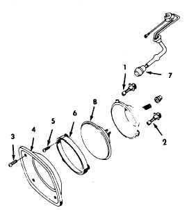
f.
To raise the light, turn the vertical adjusting
screw (1) clockwise. To lower the light, turn
the vertical adjusting screw (1) counterclock-
wise.
g.
To turn the headlight to the left or vertical, turn
the horizontal adjusting screw (2) clockwise.
To turn the headlight to the right of vertical,
turn the horizontal adjusting screw (2) counter-
clock-wise.
REMOVAL
a.
Remove four retaining screws (3) and remove
headlight bezel (4).
b.
Remove three retaining screws (5) and remove
sealed beam unit retaining ring (6).
c.
Pull sealed beam unit from headlight assem-
bly. Disconnect three-way wiring connector
(7)from rear of sealed beam unit (8) and re-
move sealed beam unit (8).
REPAIR
Repair consists of replacing defective sealed
beam unit (8) or bezel (4).
INSTALLATION
a.
Connect three-way wiring connector (7) to new
sealed beam unit (8).
b.
Position sealed beam unit (8) in mounting ring.
Install retaining ring (6) and secure with screws
(5).
CAUTION
Do not overtighten bezel retaining screws.
Overtightening
could
cause
damage
(stripping) of threads in hood fender).
c.
Install headlight bezel (4) and secure with
screws (3).
d.
Connect battery cables.
e.
Check light operation.
4-107
|