|
| |
TM5-4210-229-14&P
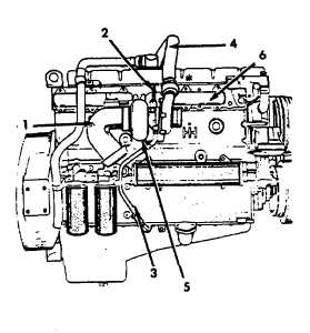
4-87. TURBOCHARGER REPLACEMENT (Continued).
d.
Make certain that the oil inlet (2) and oil drain
lines (3) are clean. If hoses are used, make
certain that they have not hardened and that
the inner lining has not deteriorated or started
to flake off. If metal tubing is used, make cer-
tain
that it is not restricted or collapsed.
e.
Install the oil inlet (2) and drain lines (3) to the
crankcase and turbocharger center housing
rotating the turbocharger center housing to
align the oil lines.
f.
When alignment has been accomplished
scribe a mark on the center and turbine hous-
ings for reference.
g.
Rotate the compressor housing to align the air
crossover tube (4) and hoses to the intake
manifold.
h.
Scribe a reference mark on the center and
compressor housing.
i.
Remove turbocharger from the engine and with
scribe marks in alignment, tighten the clamp
and torque bolts to 100-130 ft-lb (11.3-14.7
N.m) and bend the lock tabs on the lock-plates
to secure bolts.
j.
Spin the wheels of the turbocharger (5). The
shaft must rotate with no interference at either
end of the turbocharger (5).
k.
Install the four mounting bolts and nuts on ex-
haust manifold (6). Torque the bolts and nuts
to 35 ft-lb (47 N.m).
l.
Install the exhaust outlet system.
m.
Remove the covers or plugs from the oil inlet
and outlet parts. Using a new gasket, connect
the oil outlet tube (2).
n.
With a squirt can, put four or five ounces of
clean oil (Appendix D, Item 37) into the oil inlet
opening of the turbocharger (5). This will pro-
vide sufficient lubrication for the turbocharger
bearings until normal engine lubrication is es-
tablished.
o.
Connect the oil inlet tube (2) to the turbo-
charger (5) using a new gasket.
p.
Connect the air crossover tube (4) and hoses to
the compressor housing outlet and tighten the
clamps.
q.
Connect the air cleaner turbocharger connect-
ing hardware.
NOTE
Maximum allowable inlet restriction meas-
ured under full load varies according to the
application but is always less than 30 in.
H20.
r.
Intake restriction should be measured with the
engine under full load (maximum turbocharger
air flow) after turbocharger replacement.
s.
Connect battery cables.
4-100
|