|
| |
TM5-4210-229-14&P
4-41. MOTOR REPLACEMENT (Continued).
INSTALLATION
a.
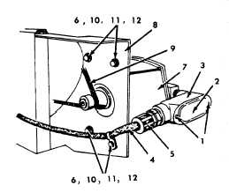
Position motor (7) to mounting bracket (8) and secure with four bolts (12), washers (11), lockwashers (10) and
nuts (6).
b.
Slide motor (7) onto drive chain (9) and tighten nuts (6) and bolts
(12).
c.
Install control wiring (4) into junction box (3) and secure with nut
(5).
d.
Connect control wiring cable (4).
e.
Position cover plate (2) to junction box (3) and secure with two
screws (1).
4-42. SWIVEL JOINT/ELBOW REPLACEMENT.
This task covers:
a.
Removal
b. Installation
INITIAL SET-UP
Tools
General Safety Instructions
General Mechanics Tool Kit
Engine OFF.
Pipe Wrench
Transmission in (N) neutral.
Parking brake set.
Materials/Parts
Battery selector switch OFF.
Swivel Joint (327078)
Elbow (327075)
Equipment Condition
Para.
Condition Description
2-23
Pressure Relieved in System
4-40
Hoses Removed
REMOVAL
NOTE
This procedure is typical for both hose
reel outlet assemblies.
a.
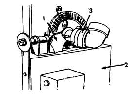
Tighten brake (1) on hose reel (2) and turn swivel
(3) off hose reel using a pipe wrench.
b.
Remove swivel joint (3).
INSTALLATION
NOTE
This procedure is typical for both hose
reel outlet assemblies.
a.
Install swivel (3) to hose reel (2) assembly and
secure using a pipe wrench.
b.
Reconnect hoses (paragraph 4-40).
c.
Pressurize the system (paragraphs 2-24 or 2-25).
4-57
|


