|
| |
TM5-4210-229-14&P
4-22. INVERTER MAINTENANCE (Continued).
NOTE
To allow twin agent 4x4 firefighting truck to be
operational while inverter is out, continue as
follows.
i.
Attach adapter harness located on the small
control harness (4) to printed circuit board con-
nector located in the control box (3).
j.
Mount the control box (3) to the inverter bracket
using the control box mounting hardware.
Ground green ground wire on the mounting
hardware.
k.
Separate the red and black power harness con-
nectors (5) and plug them into each other to con-
nect the alternator to the batteries.
l.
The voltage regulator in the control box (3) con-
trols the vehicle alternator while inverter is not
operational or not installed.
m.
Connect positive and negative terminals to bat-
teries.
INSTALLATION
NOTE
If firefighting truck was wired to operate
without inverter, begin installation pro-
cedures as follows. If not, begin in-
stallation procedures at step d.
a.
Disconnect the alternator from the batteries by
unplugging the red and black power harness
connectors.
b.
Remove the control box (3) from the inverter
bracket by removing the control box mounting
hardware. Remove the green ground wire from
the mounting hardware.
c.
Disconnect adapter harness located on the small
control harness from the printed circuit board
connector located in the control box (3).
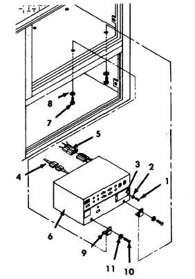
d.
If removed, attach brackets (9) to inverter (6)
using four washers (11) and bolts (10).
e.
Position inverter (6) into compartment and se-
cure with four washers (8) and mounting screws
(7).
f.
Remove tags and connect two circuit breaker
wires to inverter (6).
g.
Connect control (4) and power harness (5) on
rear of inverter.
h.
Install control box (3).
i.
Install four lockwashers (2) and screws (1) to
control box (3).
j.
Connect remote control plug.
k.
Connect positive and negative terminals to bat-
teries.
TEST
a.
Run engine at approximately 1500 rpm with in-
verter operating at 120 VAC output.
b.
Apply normal AC load. If not available, simulate
load with equivalent wattage and type of load.
c.
If AC load does not operate properly, inverter
output voltage drops more than 10 volts, or in-
verter shuts off, remove AC load.
d.
If unable to achieve stable operation, refer to
paragraph 4-11.
4-36
|