 |
|||
|
|
|||
|
|
|||
| ||||||||||
|
|
 TM 5-4210-224-14 & P
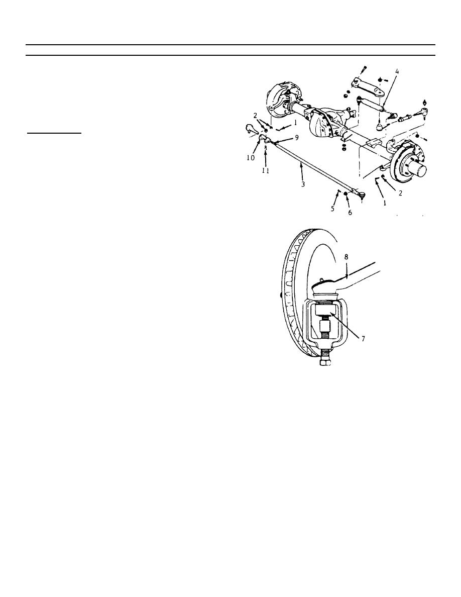
4-223. TIE RODS REPLACEMENT. (Continued)
e. Remove the tie rod end bodies (9) counting the
number of turns needed to remove them.
f. Remove the tie rod ends from the adjuster tube
(10). Note the position of the adjuster tube and
the direction from which the bolts (11) are
installed.
INSTALLATION
a. Install the tie rod end bodies to the tie rod (if
removed). Screw the rod assembly on the
same number of turns as when removed.
b. Install the tie rod ends to the adjuster tube (10),
referencing the previous position of the adjuster
tube and the direction from which they were
installed.
c. Install the outer tie rod ball studs (7) to the
steering knuckle (8).
d. Connect the shock absorber (4) to the tie rod
assembly and install the castellated nut, torque
to 46 ft-lbs (62 N.m).
e. Install the tie rod (9) end to steering knuckle (8)
castellated nuts and torque to 40 ft-lbs (55 N.m).
f. Advance all castellated nuts to align the nut slot
with the cotter pin hole and install a new cotter
pin of the correct size.
NOTE
Never back the nut off to align the
cotter pin hole.
g. Torque the jam nut at the tie rod end bodies (9)
to 92 ft-lbs (125 N.m).
h. Torque the adjuster tube clamp bolts to 40 ft-lbs
(55 N.m).
i. Lower vehicle.
4-310
|
|
Privacy Statement - Press Release - Copyright Information. - Contact Us |
