 |
|||
|
|
|||
|
|
|||
| ||||||||||
|
|
 TM 5-4210-224-14&P
1-9. LOCATION AND DESCRIPTION OF MAJOR COMPONENTS. (Continued)
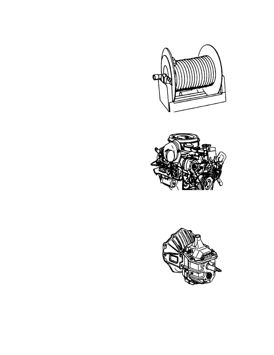
(10) Booster Hose Reel. One booster
hose reel is mounted in the rear
compartment of the truck. Three
50-foot lengths of one inch inside
diameter hose are installed on the
hose reel.
A one inch
combination adjustable fog spray
and straight stream handline
nozzle is provided with the
booster hose. An electric motor
rewinds the hose.
A manual
crank is provided in case of motor
failure.
FIGURE 1-11. BOOSTER HOSE REEL
(11) Engine. The engine is a 4 cycle,
6.2 liter, 379 Cu. In. V-8 diesel,
rated at 246 horsepower at 2,000
RPM. The engine is equipped
with an oil cooler, full flow oil
filter, fuel oil strainer, fuel oil filter,
air cleaner, fan, emission control
system, starting motor, and a dual
exhaust system.
(12) Transmission. The transmission
provides four forward speeds and
one reverse, using a constant
mesh first gear and synchronized
second, third and fourth gears.
Gear shifting is done with a
FIGURE 1-12. ENGINE
transmission cover mounted shift
lever.
The transmission also
provides a transfer case which is
located behind the transmission
and allows drive torque to be
transmitted in a proportional split
to both the front and rear axles,
resulting in four wheel drive. The
shift control lever for the transfer
case is floor mounted in the cab.
FIGURE 1-13. TRANSMISSION
FIGURE
FIGURE 1-13. TRANSMISSION
1-10
|
|
Privacy Statement - Press Release - Copyright Information. - Contact Us |
