|
| |
TM 5-4210-220-34
2-12.
PUMP DRIVE AND PTO - Continued
2-12.4 Reducer Gearbox - Continued
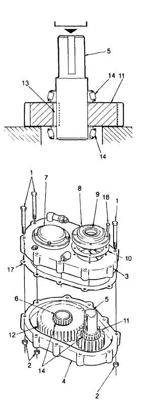
(20) Install the key (13) in shaft (5) key seat.
(21) Position the gear (11) on the press bed.
(22) Support the shaft (5) over the gear (11). Be
sure the drive end of the shaft is up, the
shaft is centered and the key (13) is alined
with the keyway in the gear.
(23) Press shaft (5) into high speed gear (11).
Be sure the gear is centered over the key
(13) so that when the bearings (14) are
installed they butt against the gear and not
the key.
(24) Press bearing cone (14) onto shaft (5) until
it contacts the gear (11). When installing
bearing cone, apply pressure to inner race.
(For low speed shaft only, install spacer
between gear and bearing).
(25) Invert shaft assembly and press other
bearing cone (14) onto opposite end of
shaft (5) until it contacts the gear (11).
When
installing
bearing
cone,
apply
pressure to inner race. (For low speed
shaft only, Install spacer between gear and
bearing.)
(26) If disassembled, press bearing cups into
the open caps (8) and closed caps (7).
Make sure the cap bore is free of dirt so the
cups will seat squarely. Do not install seals
at this time.
(27) Attach one open cap (8) and one closed
cap (7) to the lower housing half (4) using
capscrews (18). Be sure to install three
gaskets (10) under each cap. Tighten
capscrews evenly to 28 ft lb (38 Nm).
(28) Position low speed shaft assembly (6) and
high speed shaft assembly (5) in the lower
housing half (4). Rotate the shafts by hand
to mesh the helical gears.
(29) Position new gasket (17) on lower housing
half (4) and carefully lower the upper
housing half (3) onto the lower housing half
(4).
2-90
|

