|
| |
TM 5-4210-220-34
2-12.
PUMP DRIVE AND PTO - Continued
2-12.1
Power Take Off Unit - Continued
(26) Lubricate O-ring (48) with petroleum jelly (item
21, Appendix B) and install into idler shaft
hole groove. Groove is located in companion
flanged end of PTO housing (1).
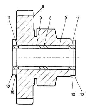
(27) Clamp cluster gear (6) in a vise. Use soft
jaws to eliminate the possibility of damage.
(28) Lubricate spacer (8) with petroleum jelly (item
21, Appendix B) and install into cluster gear
(6).
(29) Apply approximately a 1/8 in. thick film of
petroleum jelly (item 21, Appendix B) to the
inner bore of the cluster gear (6).
(30) Carefully install needle bearings (9), one by
one, until all 21 needle bearings are Installed.
Repeat this procedure for the second set of 21
needle bearings on the opposite side of the
spacer (8).
(31) Install spacers (11) into each end of the
cluster gear (6).
(32) Slide dummy shaft (9, Appendix D) into cluster gear (6) to hold all components in position.
(33) Install one thrust bearing (10) and one thrust race (12) onto each end of the dummy shaft.
(34) Carefully install the cluster gear assembly (6) in the PTO housing (1). Mesh the small gear of the cluster
gear with the gear on the spider gear assembly (24). Aline the dummy shaft with the idler shaft hole.
(35) Lubricate idler shaft (7) using petroleum jelly (item 21, Appendix B) and position over the idler shaft hole
on the oil supply end of the PTO housing (1). Make sure to aline the retainer plate slot with the position
of the retainer plate (4).
(36) Carefully press idler shaft (7) into idler shaft hole of PTO housing (1). Stop once the retainer plate (4)
can be installed into the groove of the idler shaft (7).
(37) Position retainer plate (4) in groove on idler shaft (7) and attach to PTO housing using capscrew (5).
Torque capscrew to 16 ft lb (22 Nm).
(38) Install inspection plug’(3) and gasket (2) into PTO housing (1) and torque to 50 ft lb (68 Nm).
(9)
Make sure the cluster gear (6) rotates freely, and clearance does not exceed .020 in. (0.5 mm). If
clearance exceeds previous figure replace thrust races (12), reassemble and recheck clearance.
(40) Install power take off unit as detailed in TM 5-4210-220-12.
2-76 ( 2-77 Blank)
|

